http://groups.google.com/group/sci.electronics.repair?hl=en
sci.electronics.repair@googlegroups.com
Today's topics:
* High wattage dummy load/s for audio use - 9 messages, 7 authors
http://groups.google.com/group/sci.electronics.repair/t/275ffe5cac06cb9b?hl=en
* paypal wholesale Lacoste T-Shirt woman - 1 messages, 1 author
http://groups.google.com/group/sci.electronics.repair/t/74be7a86f4da3829?hl=en
* paypal wholesale 2010 FIFA World Cup Mexico football jersey - 1 messages, 1
author
http://groups.google.com/group/sci.electronics.repair/t/54323b5ebf2a186f?hl=en
* Pioneer CDJ-1000 Mk3 ... - 1 messages, 1 author
http://groups.google.com/group/sci.electronics.repair/t/bd724168793aed39?hl=en
* TSA shaving mirror out of a hard disk drive (what are those shiny platters
made out of anyway)? - 2 messages, 2 authors
http://groups.google.com/group/sci.electronics.repair/t/680b452b6da0d742?hl=en
* Vertical Lines - 9 messages, 4 authors
http://groups.google.com/group/sci.electronics.repair/t/7824ada624c770ad?hl=en
* DATAMAN s4 eprom programmer , looking for GAL adaptor... - 2 messages, 2
authors
http://groups.google.com/group/sci.electronics.repair/t/2b308026e5f71b8d?hl=en
==============================================================================
TOPIC: High wattage dummy load/s for audio use
http://groups.google.com/group/sci.electronics.repair/t/275ffe5cac06cb9b?hl=en
==============================================================================
== 1 of 9 ==
Date: Wed, Jun 23 2010 12:48 am
From: "N_Cook"
Just curious about these - how were they used? All that is known is they
came from an audio lab.
About 200 watt, 2.8 ohm vitreous resistors. 200watt estimated, by me, from
surface area scaling of 2.5 and 6W ones, these are 210 mm long 35mm
diameter. Some sort of multiple series and parallel for 2 ohm etc or with L
and C for speaker simulation ?
== 2 of 9 ==
Date: Wed, Jun 23 2010 4:39 am
From: Tim Schwartz
On 6/23/2010 3:48 AM, N_Cook wrote:
> Just curious about these - how were they used? All that is known is they
> came from an audio lab.
> About 200 watt, 2.8 ohm vitreous resistors. 200watt estimated, by me, from
> surface area scaling of 2.5 and 6W ones, these are 210 mm long 35mm
> diameter. Some sort of multiple series and parallel for 2 ohm etc or with L
> and C for speaker simulation ?
>
>
Nigel,
To me 2.8 ohms is an odd value. I have DALE 8 ohm 250 watt, non
inductive winding resistors. With four of them, I have 8 ohms at 250
watts, or 4 ohms at 500 watts. If I had felt the need I could have done
some more complicated switching and also had 16 ohms at 500 watts.
They are very useful as you can hook them up as a dummy load and view
on your scope, and run rather large amp right up to clipping, all while
not having to listen to any of it. It also makes it easy to measure
power at clipping, as long as you also monitor your mains voltage. (At
clipping, you have to watch the voltage drop at your bench outlet, as
you might be feeding the amp a lower mains voltage than it is specified
for, which will reduce power output. I have a VARIAC to correct for this.)
I have seen one manufactured unit that used 7.87 ohm resistors, as they
figured out the resistance of the wiring and switching. I put together
my own, and did not feel the need for that level of accuracy.
The loads that I have are resistive, so not as difficult to drive as a
speaker might be, but again, good enough for my needs.
You did not specify the make or model of the resistors, or how they
were wired up.
Regards,
Tim Schwartz
Bristol Electronics
== 3 of 9 ==
Date: Wed, Jun 23 2010 6:23 am
From: Meat Plow
On Wed, 23 Jun 2010 08:48:22 +0100, N_Cook ǝʇoɹʍ:
> Just curious about these - how were they used? All that is known is they
> came from an audio lab.
> About 200 watt, 2.8 ohm vitreous resistors. 200watt estimated, by me,
> from surface area scaling of 2.5 and 6W ones, these are 210 mm long 35mm
> diameter. Some sort of multiple series and parallel for 2 ohm etc or
> with L and C for speaker simulation ?
Most newer SS amps are rated to a minimum of 2 ohms.
== 4 of 9 ==
Date: Wed, Jun 23 2010 6:50 am
From: "N_Cook"
Tim Schwartz <tim@bristolnj.com> wrote in message
news:4C21F254.1010302@bristolnj.com...
> On 6/23/2010 3:48 AM, N_Cook wrote:
> > Just curious about these - how were they used? All that is known is they
> > came from an audio lab.
> > About 200 watt, 2.8 ohm vitreous resistors. 200watt estimated, by me,
from
> > surface area scaling of 2.5 and 6W ones, these are 210 mm long 35mm
> > diameter. Some sort of multiple series and parallel for 2 ohm etc or
with L
> > and C for speaker simulation ?
> >
> >
>
> Nigel,
>
> To me 2.8 ohms is an odd value. I have DALE 8 ohm 250 watt, non
> inductive winding resistors. With four of them, I have 8 ohms at 250
> watts, or 4 ohms at 500 watts. If I had felt the need I could have done
> some more complicated switching and also had 16 ohms at 500 watts.
>
> They are very useful as you can hook them up as a dummy load and view
> on your scope, and run rather large amp right up to clipping, all while
> not having to listen to any of it. It also makes it easy to measure
> power at clipping, as long as you also monitor your mains voltage. (At
> clipping, you have to watch the voltage drop at your bench outlet, as
> you might be feeding the amp a lower mains voltage than it is specified
> for, which will reduce power output. I have a VARIAC to correct for
this.)
>
> I have seen one manufactured unit that used 7.87 ohm resistors, as they
> figured out the resistance of the wiring and switching. I put together
> my own, and did not feel the need for that level of accuracy.
>
> The loads that I have are resistive, so not as difficult to drive as a
> speaker might be, but again, good enough for my needs.
>
> You did not specify the make or model of the resistors, or how they
> were wired up.
>
> Regards,
> Tim Schwartz
> Bristol Electronics
>
Marked neatly on the curve 2R8 +/-5 % and then 87.31 perhaps 31/52 of 1987.
I picked up the last 3 at a hamfest on Sunday, I did not think to ask how
many he had originally.
I'd not googled the Arcol name stamped on the brackets as they did not look
original to the resistor section, thinking it was just a maker of steel
brackets.
Crinkle form type at top of this image
http://www.arcolresistors.com/images/product-range/wirewound/tubular-family.
jpg
but still leaves mystery of 2R8
== 5 of 9 ==
Date: Wed, Jun 23 2010 7:30 am
From: Grant
On Wed, 23 Jun 2010 13:23:04 +0000 (UTC), Meat Plow <mhywatt@yahoo.com> wrote:
>On Wed, 23 Jun 2010 08:48:22 +0100, N_Cook ??o??:
>
>> Just curious about these - how were they used? All that is known is they
>> came from an audio lab.
>> About 200 watt, 2.8 ohm vitreous resistors. 200watt estimated, by me,
>> from surface area scaling of 2.5 and 6W ones, these are 210 mm long 35mm
>> diameter. Some sort of multiple series and parallel for 2 ohm etc or
>> with L and C for speaker simulation ?
>
>Most newer SS amps are rated to a minimum of 2 ohms.
And cheapie meter leads might account for the extra 0.8 Ohms?
--
Grant.
--
http://bugs.id.au/
== 6 of 9 ==
Date: Wed, Jun 23 2010 7:59 am
From: Meat Plow
On Thu, 24 Jun 2010 00:30:47 +1000, Grant ǝʇoɹʍ:
> On Wed, 23 Jun 2010 13:23:04 +0000 (UTC), Meat Plow <mhywatt@yahoo.com>
> wrote:
>
>>On Wed, 23 Jun 2010 08:48:22 +0100, N_Cook ??o??:
>>
>>> Just curious about these - how were they used? All that is known is
>>> they came from an audio lab.
>>> About 200 watt, 2.8 ohm vitreous resistors. 200watt estimated, by me,
>>> from surface area scaling of 2.5 and 6W ones, these are 210 mm long
>>> 35mm diameter. Some sort of multiple series and parallel for 2 ohm etc
>>> or with L and C for speaker simulation ?
>>
>>Most newer SS amps are rated to a minimum of 2 ohms.
>
> And cheapie meter leads might account for the extra 0.8 Ohms? --
> Grant.
They'd have to be very cheap. Mr. Kook is a talented technician so I
think that we can rule out that factor.
I use a pair of finned 300 watt 8 ohm resistors mounted on a giant power
supply heat sink to raise their continuous rating. Got them from Yamaha
way back in the 80's when I did warranty work for their pro-audio line.
They aren't branded Yamaha. They sent them to our warranty station along
with some other equipment they required to authorize us. If I recall the
total startup cost was a couple thousand bucks but we also had a credit
line with their service/parts dept.
== 7 of 9 ==
Date: Wed, Jun 23 2010 9:10 am
From: AZ Nomad
On Thu, 24 Jun 2010 00:30:47 +1000, Grant <omg@grrr.id.au> wrote:
>On Wed, 23 Jun 2010 13:23:04 +0000 (UTC), Meat Plow <mhywatt@yahoo.com> wrote:
>>On Wed, 23 Jun 2010 08:48:22 +0100, N_Cook ??o??:
>>
>>> Just curious about these - how were they used? All that is known is they
>>> came from an audio lab.
>>> About 200 watt, 2.8 ohm vitreous resistors. 200watt estimated, by me,
>>> from surface area scaling of 2.5 and 6W ones, these are 210 mm long 35mm
>>> diameter. Some sort of multiple series and parallel for 2 ohm etc or
>>> with L and C for speaker simulation ?
>>
>>Most newer SS amps are rated to a minimum of 2 ohms.
>And cheapie meter leads might account for the extra 0.8 Ohms?
You'd need at least 90' of them (at 20 AWG)
or 8' of 30AWG, but I've never heard of such slim wire
being used for probes.
== 8 of 9 ==
Date: Wed, Jun 23 2010 9:28 am
From: zekfrivo@zekfrivolous.com (GregS)
In article <slrni24cf9.uu4.aznomad.3@ip70-176-155-130.ph.ph.cox.net>, AZ Nomad <aznomad.3@PremoveOBthisOX.COM> wrote:
>On Thu, 24 Jun 2010 00:30:47 +1000, Grant <omg@grrr.id.au> wrote:
>>On Wed, 23 Jun 2010 13:23:04 +0000 (UTC), Meat Plow <mhywatt@yahoo.com> wrote:
>
>>>On Wed, 23 Jun 2010 08:48:22 +0100, N_Cook ??o??:
>>>
>>>> Just curious about these - how were they used? All that is known is they
>>>> came from an audio lab.
>>>> About 200 watt, 2.8 ohm vitreous resistors. 200watt estimated, by me,
>>>> from surface area scaling of 2.5 and 6W ones, these are 210 mm long 35mm
>>>> diameter. Some sort of multiple series and parallel for 2 ohm etc or
>>>> with L and C for speaker simulation ?
>>>
>>>Most newer SS amps are rated to a minimum of 2 ohms.
CAR AMPS
>>And cheapie meter leads might account for the extra 0.8 Ohms?
>
>You'd need at least 90' of them (at 20 AWG)
>
>or 8' of 30AWG, but I've never heard of such slim wire
>being used for probes.
I typically get .3 ohms on the Fluke.
I have a couple dummy loads. One with 8- 50 watt gold
chassis resistors attached to sink with fan.
I have four more separate sinks without fan.
I either choose 8 ohms or 4.
greg
== 9 of 9 ==
Date: Wed, Jun 23 2010 10:20 am
From: Cydrome Leader
N_Cook <diverse@tcp.co.uk> wrote:
> Just curious about these - how were they used? All that is known is they
> came from an audio lab.
> About 200 watt, 2.8 ohm vitreous resistors. 200watt estimated, by me, from
> surface area scaling of 2.5 and 6W ones, these are 210 mm long 35mm
> diameter. Some sort of multiple series and parallel for 2 ohm etc or with L
> and C for speaker simulation ?
the ones I used were just large (hundreds of watts) ceramic wirewound
resistor mounted in heatsinks. They had to have been 8 ohms or something
really close as to not blow up 1970s and 1980s equipment.
you could hear the music though them if you got close enough.
==============================================================================
TOPIC: paypal wholesale Lacoste T-Shirt woman
http://groups.google.com/group/sci.electronics.repair/t/74be7a86f4da3829?hl=en
==============================================================================
== 1 of 1 ==
Date: Wed, Jun 23 2010 2:21 am
From: 召 贾
http://picasaweb.google.de/peopletrade.clothing002
paypal wholesale T-Shirt
paypal wholesale BAPE T-Shirt man
http://picasaweb.google.de/peopletrade.clothing002
paypal wholesale BBC T-Shirt man
paypal wholesale Boos T-shirt man
http://picasaweb.google.de/peopletrade.clothing002
paypal wholesale Coogi T-Shirt man
paypal wholesale AKoo T-shirt man
http://picasaweb.google.de/peopletrade.clothing002
ED Hardy man
paypal wholesale ED Hardy woman
paypal wholesale Gucci T-Shirt man
Affliction T-Shirt man
http://picasaweb.google.de/peopletrade.clothing002
paypal wholesale Polo T-Shirt man
paypal wholesale replica Polo T-Shirt woman
http://picasaweb.google.de/peopletrade.clothing002
paypal wholesale Juicy T-Shirt woman
paypal wholesale 2010 NEW CA T-Shirt man
http://picasaweb.google.de/peopletrade.clothing002
wholesale replica Burberry T-Shirt
wholesale replica DSQ T-Shirt man
http://picasaweb.google.de/peopletrade.clothing002
paypal wholesale Tommy T-Shirt woman
Ecko T-Shirt
paypal wholesale replica Timberland T-Shirt man
Paul Smith T-Shirt woman
Paul Smith T-Shirt man
http://picasaweb.google.de/peopletrade.clothing002
paypal wholesale Lacoste T-Shirt
http://picasaweb.google.de/peopletrade.clothing002
paypal wholesale Lacoste T-Shirt woman
Adidas T-Shirt man
factory price Big Pony Polo T-Shirt
factory price Christan Audigier woman
factory price Crown Holder man
factory price Crystal Rock woman
http://picasaweb.google.de/peopletrade.clothing002
Dom Rebel man
factory price replica Nike T-Shirt
factory price Hollister T-Shirt man
http://picasaweb.google.de/peopletrade.clothing002
Dsquared T-Shirt woman
wholesale replica Remetee T-Shirt man
wholesale replica Frankie Morello man
http://picasaweb.google.de/peopletrade.clothing002
wholesale replica replica Sinful T-Shirt man
Tapout T-Shirt man
wholesale replica Rocawear T-Shirt
http://picasaweb.google.de/peopletrade.clothing002
wholesale replica A2&Michael Jackson
==============================================================================
TOPIC: paypal wholesale 2010 FIFA World Cup Mexico football jersey
http://groups.google.com/group/sci.electronics.repair/t/54323b5ebf2a186f?hl=en
==============================================================================
== 1 of 1 ==
Date: Wed, Jun 23 2010 2:24 am
From: 召 贾
paypal wholesale 2010 FIFA World Cup Barcelona jersey
http://picasaweb.google.ca/113858744773724803250/
paypal wholesale 2010 FIFA World Cup Barcelona jersey
http://picasaweb.google.ca/113858744773724803250/
paypal wholesale 2010 FIFA World Cup Barcelona jersey
http://picasaweb.google.ca/113858744773724803250/
paypal wholesale 2010 FIFA World Cup Argentina football jersey
http://picasaweb.google.ca/113858744773724803250/Argentina#
paypal wholesale 2010 FIFA World Cup Argentina football jersey
http://picasaweb.google.ca/113858744773724803250/Argentina#
paypal wholesale 2010 FIFA World Cup Argentina football jersey
http://picasaweb.google.ca/113858744773724803250/Argentina#
http://picasaweb.google.ca/113858744773724803250
Manchester United FootballClub jersey paypal wholesale 2010 FIFA
World
Cup Manchester
http://picasaweb.google.ca/113858744773724803250
Manchester United FootballClub jersey paypal wholesale 2010 FIFA
World
Cup Manchester
http://picasaweb.google.ca/113858744773724803250
Manchester United FootballClub jersey paypal wholesale 2010 FIFA
World
Cup Manchester
paypal wholesale 2010 FIFA World Cup Brazil football jersey
http://picasaweb.google.ca/113858744773724803250
paypal wholesale 2010 FIFA World Cup Brazil football jersey
http://picasaweb.google.ca/113858744773724803250
paypal wholesale 2010 FIFA World Cup Brazil football jersey
http://picasaweb.google.ca/113858744773724803250
paypal wholesale 2010 FIFA World Cup Brazil football jersey
http://picasaweb.google.ca/113858744773724803250
paypal wholesale 2010 FIFA World Cup Manchester United Football Club
football jersey
http://picasaweb.google.ca/113858744773724803250
paypal wholesale 2010 FIFA World Cup Manchester United Football Club
football jersey
http://picasaweb.google.ca/113858744773724803250
paypal wholesale 2010 FIFA World Cup Manchester United Football Club
football jersey
http://picasaweb.google.ca/113858744773724803250
paypal wholesale 2010 FIFA World Cup Manchester United Football Club
football jersey
http://picasaweb.google.ca/113858744773724803250
paypal wholesale 2010 FIFA World Cup Manchester United Football Club
football jersey
http://picasaweb.google.ca/113858744773724803250
paypal wholesale 2010 FIFA World Cup Brazil football jersey
http://picasaweb.google.ca/113858744773724803250
paypal wholesale 2010 FIFA World Cup England football jersey
http://picasaweb.google.ca/113858744773724803250
paypal wholesale 2010 FIFA World Cup France football jersey
paypal wholesale 2010 FIFA World Cup New Zealand football jersey
http://picasaweb.google.ca/113858744773724803250
paypal wholesale 2010 FIFA World Cup Portugal football jersey
paypal wholesale 2010 FIFA World Cup Germany football jersey
paypal wholesale 2010 FIFA World Cup Italy football jersey
http://picasaweb.google.ca/113858744773724803250
paypal wholesale 2010 FIFA World Cup Spain football jersey
paypal wholesale 2010 FIFA World Cup Turkey football jersey
paypal wholesale 2010 FIFA World Cup South Africa football jersey
paypal wholesale 2010 FIFA World Cup Holland football jersey
http://picasaweb.google.ca/113858744773724803250
paypal wholesale 2010 FIFA World Cup Mexico football jersey
paypal wholesale 2010 FIFA World Cup Greece football jersey
paypal wholesale 2010 FIFA World Cup Argentina football jersey
http://picasaweb.google.ca/113858744773724803250
paypal wholesale 2010 FIFA World Cup Russia football jersey
paypal wholesale 2010 FIFA World Cup Algeria football jersey
paypal wholesale 2010 FIFA World Cup Cameroon football jersey
http://picasaweb.google.ca/113858744773724803250
paypal wholesale 2010 FIFA World Cup Cote D'Ivoire football jersey
==============================================================================
TOPIC: Pioneer CDJ-1000 Mk3 ...
http://groups.google.com/group/sci.electronics.repair/t/bd724168793aed39?hl=en
==============================================================================
== 1 of 1 ==
Date: Wed, Jun 23 2010 3:44 am
From: "Arfa Daily"
"Meat Plow" <mhywatt@yahoo.com> wrote in message
news:pan.2010.06.22.13.46.50@gmail.com...
> On Tue, 22 Jun 2010 13:47:00 +0100, Arfa Daily ǝʇoɹʍ:
>
>> Anyone know if this pro DJ unit has a mode whereby the button
>> function-sensitive backlighting can be turned off ? I've not seen a Mk3
>> before, and don't have the manual for it. The one that I've just fixed
>> was in for a mechanical problem on the deck, which was straightforward
>> enough. All of the buttons work and do as they should, but none light up
>> when pressed. The "Vinyl - CDJ" indicators don't light either, although
>> the central jog display correctly shows "Vinyl" or nothing, when the
>> button is operated. There's so many different LEDs involved here, that
>> it seems unlikely that there is any 'fault' as such, and the job ticket
>> doesn't mention any such problem, so I'm wondering if a soft switch-off
>> function has been put in, to stop the console looking too 'busy' in the
>> dark, if some DJs prefer it that way. Or possibly I suppose, if all the
>> LEDs are taken up to some common supply rail that's just for them, there
>> might be some little wire ended or sm fuse, as Pioneer are so fond of
>> using in '1000s ?? Anyone know ?
>
> With all the lights and commotion in a club where you would find pro dj
> equip I would think that some console lights would hardly be a
> distraction warranting dimming.
Yep - quite right. It was in fact a genuine fault. There are many picofuses
on the MJCB board, and one of these feeds 12v out on a rail called "VLED".
Bit of a giveaway, really ...
For future reference for anyone who might be interested, it is IC1513, and
is rated at T315mA. Replacing it restored all the LEDs to normal operation.
My thanks, as ever, to Mark Z, who managed to find a copy of the schematics
for me. Cheers Mark - it was a big help :-)
Arfa
==============================================================================
TOPIC: TSA shaving mirror out of a hard disk drive (what are those shiny
platters made out of anyway)?
http://groups.google.com/group/sci.electronics.repair/t/680b452b6da0d742?hl=en
==============================================================================
== 1 of 2 ==
Date: Wed, Jun 23 2010 6:06 am
From: Sylvia Else
On 22/06/2010 2:48 PM, Elmo wrote:
> What are the shiny CDROM-sized platters in an old desktop disk drive made
> out of?
>
> I glued two of them together so that the offset covered the center hole to
> use as an indestructable traveling shaving mirror.
>
> A friend said they won't pass TSA security
You're suggesting that TSA use any sort of rational criterion when
deciding what to let through?
Sylvia.
== 2 of 2 ==
Date: Wed, Jun 23 2010 10:02 am
From: TimR
On Jun 22, 6:40 pm, "Rod Speed" <rod.speed....@gmail.com> wrote:
> Elmo wrote:
>
> I wouldnt like to predict what some trained ape will make of them.
I wouldn't take a chance.
I'd put them in a protective sleeve. I'd use one of those free AOL
disk sleeves you find in piles everywhere.
==============================================================================
TOPIC: Vertical Lines
http://groups.google.com/group/sci.electronics.repair/t/7824ada624c770ad?hl=en
==============================================================================
== 1 of 9 ==
Date: Wed, Jun 23 2010 6:24 am
From: Meat Plow
On Tue, 22 Jun 2010 20:08:53 -0400, DB ǝʇoɹʍ:
> "DB" <x@x.com> wrote in message
> news:deadnRItKurh1rzRnZ2dnUVZ_rCdnZ2d@earthlink.com...
>> Have a Toshiba 30HF85 30" TV. There are vertical lines at the top of
>> the screen. I believe I need to replace the cap near the vertical hold
>> IC. Where is the vertical hold IC? Thanks.
>>
>>
> Mistake!! I have horizontal lines near top of screen!! Sorry.
Take it to a repair shop before you hurt yourself or worse.
== 2 of 9 ==
Date: Wed, Jun 23 2010 7:18 am
From: "DB"
"DB" <x@x.com> wrote in message
news:vLmdnX7vEcXgzbzRnZ2dnUVZ_qCdnZ2d@earthlink.com...
>
> "DB" <x@x.com> wrote in message
> news:deadnRItKurh1rzRnZ2dnUVZ_rCdnZ2d@earthlink.com...
>> Have a Toshiba 30HF85 30" TV. There are vertical lines at the top of the
>> screen. I believe I need to replace the cap near the vertical hold IC.
>> Where is the vertical hold IC? Thanks.
>>
>
> Mistake!! I have horizontal lines near top of screen!! Sorry.
>
Listen guys. I have a 2 year degree in elect/electronics. I know all about
the high voltage. I've been inside many a crt's without getting fried. I
once fixed a crt monitor by replacing a dead cap. I appreciate the concern.
New development: I realized it's as if the picture size has been increased
vertically to where the image has returned at the top but upside down. Is
there an adjustment or do I need to replace a component? Thanks.
== 3 of 9 ==
Date: Wed, Jun 23 2010 7:31 am
From: Meat Plow
On Wed, 23 Jun 2010 10:18:24 -0400, DB ǝʇoɹʍ:
> "DB" <x@x.com> wrote in message
> news:vLmdnX7vEcXgzbzRnZ2dnUVZ_qCdnZ2d@earthlink.com...
>>
>> "DB" <x@x.com> wrote in message
>> news:deadnRItKurh1rzRnZ2dnUVZ_rCdnZ2d@earthlink.com...
>>> Have a Toshiba 30HF85 30" TV. There are vertical lines at the top of
>>> the screen. I believe I need to replace the cap near the vertical
>>> hold IC. Where is the vertical hold IC? Thanks.
>>>
>>>
>> Mistake!! I have horizontal lines near top of screen!! Sorry.
>>
>>
> Listen guys. I have a 2 year degree in elect/electronics.
I have a 35 year degree in experience on the job. The structure of your
questions are a dead giveaway (no pun intended) that you should not be
inside the back of a set relying on your associates degree to protect you.
That is unless you wrap it around your hand as an insulator.
== 4 of 9 ==
Date: Wed, Jun 23 2010 7:42 am
From: "DB"
"DB" <x@x.com> wrote in message
news:vLmdnX7vEcXgzbzRnZ2dnUVZ_qCdnZ2d@earthlink.com...
>
> "DB" <x@x.com> wrote in message
> news:deadnRItKurh1rzRnZ2dnUVZ_rCdnZ2d@earthlink.com...
>> Have a Toshiba 30HF85 30" TV. There are vertical lines at the top of the
>> screen. I believe I need to replace the cap near the vertical hold IC.
>> Where is the vertical hold IC? Thanks.
>>
>
> Mistake!! I have horizontal lines near top of screen!! Sorry.
>
I believe it's called vertical fold over. I most likely need to replace a
bad cap near the vertical hold IC.
Which takes me back to my original question: Where is the vertical hold IC?
What's the shape and how many pins? Thanks.
== 5 of 9 ==
Date: Wed, Jun 23 2010 7:44 am
From: "DB"
"Meat Plow" <mhywatt@yahoo.com> wrote in message
news:pan.2010.06.23.14.32.45@gmail.com...
> On Wed, 23 Jun 2010 10:18:24 -0400, DB ??o??:
>
>
>> "DB" <x@x.com> wrote in message
>> news:vLmdnX7vEcXgzbzRnZ2dnUVZ_qCdnZ2d@earthlink.com...
>>>
>>> "DB" <x@x.com> wrote in message
>>> news:deadnRItKurh1rzRnZ2dnUVZ_rCdnZ2d@earthlink.com...
>>>> Have a Toshiba 30HF85 30" TV. There are vertical lines at the top of
>>>> the screen. I believe I need to replace the cap near the vertical
>>>> hold IC. Where is the vertical hold IC? Thanks.
>>>>
>>>>
>>> Mistake!! I have horizontal lines near top of screen!! Sorry.
>>>
>>>
>> Listen guys. I have a 2 year degree in elect/electronics.
>
> I have a 35 year degree in experience on the job. The structure of your
> questions are a dead giveaway (no pun intended) that you should not be
> inside the back of a set relying on your associates degree to protect you.
> That is unless you wrap it around your hand as an insulator.
I've already been in there. You're not responsible. Which IC is it?
Thanks.
== 6 of 9 ==
Date: Wed, Jun 23 2010 8:16 am
From: stratus46@yahoo.com
On Jun 23, 7:44 am, "DB" <x...@x.com> wrote:
> "Meat Plow" <mhyw...@yahoo.com> wrote in message
>
> news:pan.2010.06.23.14.32.45@gmail.com...
>
>
>
>
>
> > On Wed, 23 Jun 2010 10:18:24 -0400, DB ??o??:
>
> >> "DB" <x...@x.com> wrote in message
> >>news:vLmdnX7vEcXgzbzRnZ2dnUVZ_qCdnZ2d@earthlink.com...
>
> >>> "DB" <x...@x.com> wrote in message
> >>>news:deadnRItKurh1rzRnZ2dnUVZ_rCdnZ2d@earthlink.com...
> >>>> Have a Toshiba 30HF85 30" TV. There are vertical lines at the top of
> >>>> the screen. I believe I need to replace the cap near the vertical
> >>>> hold IC. Where is the vertical hold IC? Thanks.
>
> >>> Mistake!! I have horizontal lines near top of screen!! Sorry.
>
> >> Listen guys. I have a 2 year degree in elect/electronics.
>
> > I have a 35 year degree in experience on the job. The structure of your
> > questions are a dead giveaway (no pun intended) that you should not be
> > inside the back of a set relying on your associates degree to protect you.
> > That is unless you wrap it around your hand as an insulator.
>
> I've already been in there. You're not responsible. Which IC is
it?
> Thanks.
Then buy the service manual.
G²
== 7 of 9 ==
Date: Wed, Jun 23 2010 8:15 am
From: Stefan Heimers
DB wrote:
> Which takes me back to my original question: Where is the vertical hold
> IC?
> What's the shape and how many pins? Thanks.
There are two coils on the back of the CRT. The horizontal is connected to
the horizontal output transformer (which is also the high voltage
transformer, I'm sure you recognize it).
Now just track the connection to the other coil. This comes from the
vertical output stage, which is driven by the vertical sync circuit.
If your picture is stable besides of the wrong size, its probably not the
vertical IC at fault, but the power amplifier after it, or the power
supply.
If there are only a few lines, and they are crossing the picture diagonally,
then it's the beam which is not blanked during the vertical flyback. This
can be caused by a worn out picture tube, or by the grid bias voltages. I
don't know about your TV, but usually there are some potentiometers for
adjusting the grid voltages and slightly changing it makes the lines
diasppear. That's what it lools like:
http://bs.cyty.com/menschen/e-etzold/archiv/TV/uvb/img/MC47_ohneUVB.jpg
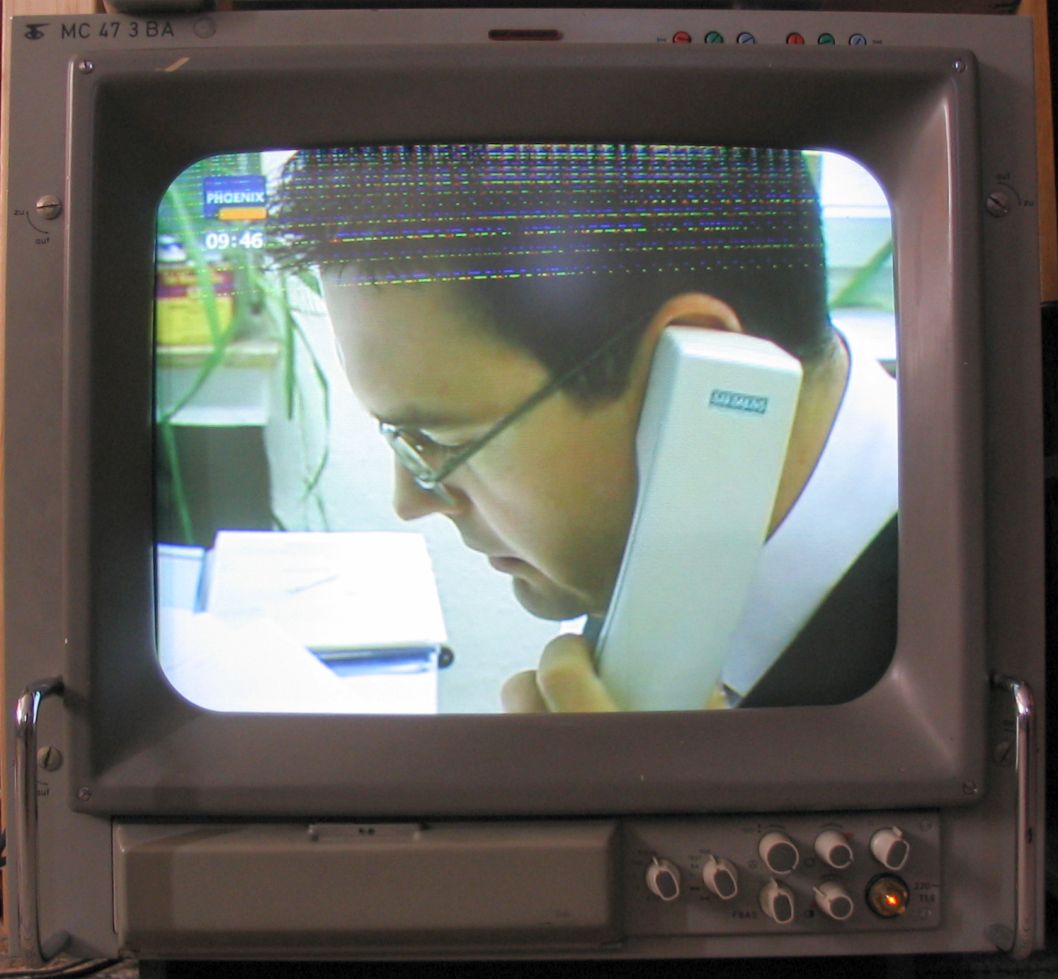
Is yours similar to that?
Stefan
== 8 of 9 ==
Date: Wed, Jun 23 2010 8:30 am
From: "DB"
"Stefan Heimers" <stefan.usenet@heimers.ch> wrote in message
news:hvt8ke$rqb$1@news.albasani.net...
> DB wrote:
>
>
>> Which takes me back to my original question: Where is the vertical hold
>> IC?
>> What's the shape and how many pins? Thanks.
>
>
> There are two coils on the back of the CRT. The horizontal is connected to
> the horizontal output transformer (which is also the high voltage
> transformer, I'm sure you recognize it).
>
> Now just track the connection to the other coil. This comes from the
> vertical output stage, which is driven by the vertical sync circuit.
>
> If your picture is stable besides of the wrong size, its probably not the
> vertical IC at fault, but the power amplifier after it, or the power
> supply.
>
> If there are only a few lines, and they are crossing the picture
> diagonally,
> then it's the beam which is not blanked during the vertical flyback. This
> can be caused by a worn out picture tube, or by the grid bias voltages. I
> don't know about your TV, but usually there are some potentiometers for
> adjusting the grid voltages and slightly changing it makes the lines
> diasppear. That's what it lools like:
>
> http://bs.cyty.com/menschen/e-etzold/archiv/TV/uvb/img/MC47_ohneUVB.jpg
>
> Is yours similar to that?
>
> Stefan
>
>
Thanks. Finally some useful info. The symptoms look more like when the
picture is adjusted to large and it folds back, to where you can see and
image in the lines, but upside down. Only about 1" at the top.
== 9 of 9 ==
Date: Wed, Jun 23 2010 10:23 am
From: Meat Plow
On Wed, 23 Jun 2010 10:44:36 -0400, DB ǝʇoɹʍ:
> "Meat Plow" <mhywatt@yahoo.com> wrote in message
> news:pan.2010.06.23.14.32.45@gmail.com...
>> On Wed, 23 Jun 2010 10:18:24 -0400, DB ??o??:
>>
>>
>>> "DB" <x@x.com> wrote in message
>>> news:vLmdnX7vEcXgzbzRnZ2dnUVZ_qCdnZ2d@earthlink.com...
>>>>
>>>> "DB" <x@x.com> wrote in message
>>>> news:deadnRItKurh1rzRnZ2dnUVZ_rCdnZ2d@earthlink.com...
>>>>> Have a Toshiba 30HF85 30" TV. There are vertical lines at the top
>>>>> of the screen. I believe I need to replace the cap near the
>>>>> vertical hold IC. Where is the vertical hold IC? Thanks.
>>>>>
>>>>>
>>>> Mistake!! I have horizontal lines near top of screen!! Sorry.
>>>>
>>>>
>>> Listen guys. I have a 2 year degree in elect/electronics.
>>
>> I have a 35 year degree in experience on the job. The structure of your
>> questions are a dead giveaway (no pun intended) that you should not be
>> inside the back of a set relying on your associates degree to protect
>> you. That is unless you wrap it around your hand as an insulator.
>
> I've already been in there. You're not responsible. Which IC is it?
> Thanks.
If you have a pdf document source for the schematic I'll have a look and
let you know.
==============================================================================
TOPIC: DATAMAN s4 eprom programmer , looking for GAL adaptor...
http://groups.google.com/group/sci.electronics.repair/t/2b308026e5f71b8d?hl=en
==============================================================================
== 1 of 2 ==
Date: Wed, Jun 23 2010 6:48 am
From: "Jps"
Hi guys.
I'm a student, and i'm entering the world of the chip programming.
I have acquired a dataman s4, and i would like to use some pal and gal chip.
I know that an adaptor it's needed, but anyone that own it know if it's
possible to build this ? Anyone know this or have some schematics?
Thank you so much from europe!
== 2 of 2 ==
Date: Wed, Jun 23 2010 8:21 am
From: WangoTango
In article <YgoUn.183178$9f6.349677@twister1.libero.it>,
formula1vhsNOSPAM@hotmail.com says...
> Hi guys.
> I'm a student, and i'm entering the world of the chip programming.
> I have acquired a dataman s4, and i would like to use some pal and gal chip.
> I know that an adaptor it's needed, but anyone that own it know if it's
> possible to build this ? Anyone know this or have some schematics?
> Thank you so much from europe!
Have you tried their website?
They use to have a listing of all the adapters AND the wiring of those
adapters, so you could make one yourself.
==============================================================================
You received this message because you are subscribed to the Google Groups "sci.electronics.repair"
group.
To post to this group, visit http://groups.google.com/group/sci.electronics.repair?hl=en
To unsubscribe from this group, send email to sci.electronics.repair+unsubscribe@googlegroups.com
To change the way you get mail from this group, visit:
http://groups.google.com/group/sci.electronics.repair/subscribe?hl=en
To report abuse, send email explaining the problem to abuse@googlegroups.com
==============================================================================
Google Groups: http://groups.google.com/?hl=en
No Response to "sci.electronics.repair - 25 new messages in 7 topics - digest"
Post a Comment