jurb6006@gmail.com: May 31 11:03PM -0700
>"Do you have waveform 73 on schematic 8? That is the B start gate. >Start there."
I have a square wave there that tracks the A sweep speed. However I see a flat line on the collector and emitter of Q4565. That makes it highly suspect.
I have to set it aside for a minute because I have a custom customer in tomorrow. But in the meantime I can figure out a decent replacement for Q4565. It is not that critical but I do have a little bit of respect for people who are that anal about designing.
Anyway, since the intensify function works off the ten turn pot pretty much correctly, but the intensified part never ends of course because B sweep doesn't start, that localizes the problem. Like I said, Q4565.
Thanks...
Now I just hope that fucker ain't germanium !
|
jurb6006@gmail.com: May 31 11:12PM -0700
>"**The 465B is a great old 'scope, BUT, like many Tektronix 'scopes >of the time, tunnel diodes are used in the sweep systems. The tunnel >diodes used are VERY hard to source. "
True, and tunnel diode triggering was the best. The thing would almost sync to white noise. My old 422 was that way. And played guitars and organs n shit into it and it always synced up, no problem. Even the human voice. Even most integrated program material (songs already recorded for those who do not know the phrase).
So, when I find something looks right for Q4565 I'll let you all know if it worked.
|
jurb6006@gmail.com: May 31 11:20PM -0700
> Uh-Oh. Something happen to Yanik?
> Mark Z.
I think so, life. I think if he is alive now he is probably about 98 years old.
I would have liked to have met him and had a couple brewskis. I mean really, and you might as well know that I have no desire to meet any President of the US within my lifetime, and then some.
Yanik was super sharp with scopes. You ask a question and he says "that is a 100K ceramic, R401 which is on the left side behind the big blue thing in the middle of the board". Some shit like that.
I got that good with TVs but they don't go for ten grand.
|
"tom" <tmiller11147@verizon.net>: Jun 01 03:13AM -0400
<jurb6006@gmail.com> wrote in message
news:7625ab4c-3522-453d-84c2-acd4cf3a48aa@googlegroups.com...
>"Do you have waveform 73 on schematic 8? That is the B start gate. >Start
>there."
I have a square wave there that tracks the A sweep speed. However I see a
flat line on the collector and emitter of Q4565. That makes it highly
suspect.
I have to set it aside for a minute because I have a custom customer in
tomorrow. But in the meantime I can figure out a decent replacement for
Q4565. It is not that critical but I do have a little bit of respect for
people who are that anal about designing.
Anyway, since the intensify function works off the ten turn pot pretty much
correctly, but the intensified part never ends of course because B sweep
doesn't start, that localizes the problem. Like I said, Q4565.
Thanks...
Now I just hope that fucker ain't germanium !
+++++++++++++++++++++++++++++++++++++++++++
No Ge transistors in the 465. It's late. I'll look at it tomorrow and
suggest a next step sans you fixing it.
|
jurb6006@gmail.com: Jun 01 12:30AM -0700
Thanks. I actually just checked it real quick with the scope but did not pay alot of attention to the DC levels. I actually don't even know the pinout yet.
But I got square waves on one pin the the on/off time varies with the ten turn pot on the front panel for delay. That puts the problem right there, I should be able to smell it.
If the circuit works they way I think, which is they are feeding the emitter of Q4565, I do not like that. I mean I think it is bad because of the readings, but I think it went bad because of the way they used it.
But really, they probably had no other choice. I have seen it before, I have done failure mode analysis. And I have found that at times, they simply had no other choice and their circuit was going to beat on this certain part.
So anyway, what to put in there. I am not going to pay eBay $37 for a 11132-0002-1005 transistor, even if it is in original packaging. (I made the number up so don't bother)
It is pretty much a common base amp, but not really used linear, I THINK. No, I am pretty sure. You see the base hard biased by the two 1K resistors making the base voltage -4 volts. And it says right there that -3 volts starts B sweep.
|
M Philbrook <jamie_ka1lpa@charter.net>: Jun 01 11:00AM -0400
In article <ab963de2-eca4-403c-8808-65d0f95c82a7@googlegroups.com>,
jurb6006@gmail.com says...
> But really, they probably had no other choice. I have seen it before, I have done failure mode analysis. And I have found that at times, they simply had no other choice and their circuit was going to beat on this certain part.
> So anyway, what to put in there. I am not going to pay eBay $37 for a 11132-0002-1005 transistor, even if it is in original packaging. (I made the number up so don't bother)
> It is pretty much a common base amp, but not really used linear, I THINK. No, I am pretty sure. You see the base hard biased by the two 1K resistors making the base voltage -4 volts. And it says right there that -3 volts starts B sweep.
They sometimes do that to isolate the voltage levels on the collector
side and keep the switching polarity the same.
Its a faster switching method if you have a HV side verses low voltage
side rather then adding a inverter stage.
CaseCode config..
I am only going by your description..
Jamie
|
Jeff Liebermann <jeffl@cruzio.com>: May 31 08:17AM -0700
On Mon, 30 May 2016 22:20:43 -0700 (PDT), curls <borskyc@yahoo.com>
wrote:
>> Most common problem I've seen on vehicle CD players is "smoke" on the
>> lenses and mirrors.
>It's 2012 Mazda 3 iGT Hatch.
My point is that the drive is NOT easily replaced. No clue on parts
but unless the CD drive mechanism can be identified, finding
replacement parts is going to be difficult.
Read the repair faq section on "CD players in vehicles".
>I know this car was a smoker's before me for 4 years.
Bingo. 90% rubbing alcohol works well to remove the tar.
>So if most of the time problems have been smoke on the lens, do you
>mean actual smokers? It'd been hopeful for me, if that's the case.
Yes, but there are plenty of other sources of oil, grease, tar, soot,
and such. Just look at the windows. Do they remain perfectly clear
when you're driving? Of course not. Well, some of that also gets
into the CD player and makes the optics looks much like your
windshield.
>Can you see in the photos, where the glass mirror would be?
I have no idea. The photos are too small and cover too large an area.
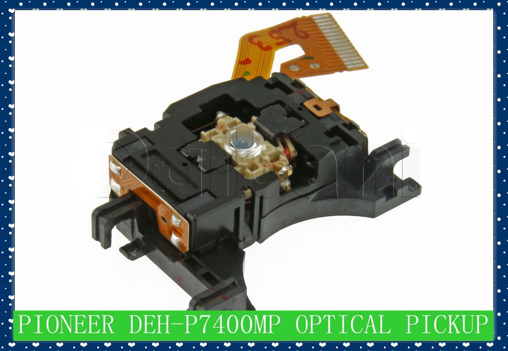
Look for something like this:
<http://g01.a.alicdn.com/kf/HTB1Cm2ZKXXXXXXWXFXXq6xXFXXXJ/Original-Replace-For-font-b-Pioneer-b-font-DEH-P7400MP-font-b-CD-b-font-font.jpg>
The mirrors are behind the lens.
<http://hyperphysics.phy-astr.gsu.edu/hbase/audio/cdplay.html>
>take a photo since it has to be in the box, where the beam isn't
>directly visible. Maybe the more cleaning that I've done
>will do the trick.
I don't take a photo. All I do is check if there's anything coming
out of the laser or if it looks wrong.
<https://www.youtube.com/watch?v=Df70YVAg-iI>
Fast forward to 2:10 for what it looks like. Not all digital cameras
can see 780nm light. (DVD are 650nm and BluRay are 405nm).
There are also photo diodes on a stick that can be used to measure the
laser output. For some odd reason, I can't find the magic buzzwords
and URL. Anyone?
Oh crap. Power outage... save, post, and run...
--
Jeff Liebermann jeffl@cruzio.com
150 Felker St #D http://www.LearnByDestroying.com
Santa Cruz CA 95060 http://802.11junk.com
Skype: JeffLiebermann AE6KS 831-336-2558
|
dplatt@coop.radagast.org (Dave Platt): May 31 01:17PM -0700
In article <2017a819-60e3-44a8-9fa9-8172b8dc4afc@googlegroups.com>,
>> In article <edc77ec8-cedd-4e17-b1f8-7c0c9da95b93@googlegroups.com>,
>Wow Dave, thanks for all the ideas!
>Any idea in brick and mortar where I can buy 99%?
I usually get it at Fry's, in the electronic-tools section.
Online... Amazon or eBay would probably work.
>I'd also like to find something that won't leave lint like a qtip has.
There are foam-tipped swabs (look a bit like Q tips on steroids)
designed for just that purpose.
>I had no idea CD books are done with a less expensive method similar to
>home burned.
These days, burning is used for a lot of smaller CD production runs.
I haven't priced things lately but I suspect it's more economical for
any single-run batches of less than a thousand copies.
|
"Ian Field" <gangprobing.alien@ntlworld.com>: May 31 10:20PM +0100
"curls" <borskyc@yahoo.com> wrote in message
news:edc77ec8-cedd-4e17-b1f8-7c0c9da95b93@googlegroups.com...
> get the radio out of the car, and opened it until I can now see the laser
> lens.
> I plan to clean with Qtip and isopropyl alcohol 91%.
You can get a lens cleaning disk with a small tuft of brush on it that wipes
the lens as it goes round. There's normally a bottle of cleaning fluid
supplied in the box.
Attacking the lens with a Q-tip is the last resort, the lens mount is very
fragile. normally that is only necessary if you're a heavy smoker and tar
deposits have contaminated the deck.
The Q-tip is pretty much the kill or cure last ditch attempt to save it!
|
Michael Black <et472@ncf.ca>: May 31 05:55PM -0400
|
Jeff Liebermann <jeffl@cruzio.com>: May 31 02:55PM -0700
On Tue, 31 May 2016 12:51:28 -0400, Ralph Mowery
>in some open containers (about half a teaspoon) and kept checking on it.
>The 90% still had something left in it after all the 99% was gone or
>almost gone.
Got a proof and tralle hydrometer? Surely a well equipped kitchen
laboratory should have one[1]. If not, check for home moonshine
making kits online. They're calibrated in percent alcohol. You want
one that goes to 200 proof (100%) alcohol:
<http://www.ebay.com/sch/i.html?_nkw=proof+and+tralle+hydrometer>
The following look good because of the expanded 70% to 100% range:
<http://www.ebay.com/itm/New-3pcs-Vinometer-Proof-and-Tralle-Hydrometer-Alcohol-meter-0-100-w-Hydrometer-/171952516675>
<http://www.ebay.com/itm/PROOF-AND-TRALLE-60-100-HYDROMETER-MEASURE-ALCOHOL-CONTENT-OF-DISTILLED-SPIRITS-/111409214376>
<http://www.banggood.com/3PCSSET-Alcohol-Meter-Hydrometer-Wine-Measuring-Instrument-Vinometer-Thermometer-p-1036683.html>
Note that these are all calibrated at some specific temperature. Have
a thermometer handy and make sure you get the necessary temperature
conversion tables.
[1] Impress your friends and relatives by measuring the alcohol
concentration of their booze.
--
Jeff Liebermann jeffl@cruzio.com
150 Felker St #D http://www.LearnByDestroying.com
Santa Cruz CA 95060 http://802.11junk.com
Skype: JeffLiebermann AE6KS 831-336-2558
|
Jeff Liebermann <jeffl@cruzio.com>: May 31 03:01PM -0700
On Tue, 31 May 2016 22:20:00 +0100, "Ian Field"
>You can get a lens cleaning disk with a small tuft of brush on it that wipes
>the lens as it goes round. There's normally a bottle of cleaning fluid
>supplied in the box.
Ahem. I once bought one of those, stuffed it into a working CD
player, and in no time produced a non-working CD player. The base of
the brush, where it attaches to the CD disk, is rather hard and stiff.
It hit the lens, mangled the springs, and killed the head assembly.
Not recommended.
--
Jeff Liebermann jeffl@cruzio.com
150 Felker St #D http://www.LearnByDestroying.com
Santa Cruz CA 95060 http://802.11junk.com
Skype: JeffLiebermann AE6KS 831-336-2558
|
dplatt@coop.radagast.org (Dave Platt): May 31 03:37PM -0700
In article <d82skbtde1oj7vgichdhhfruabjco6sdj1@4ax.com>,
>the brush, where it attaches to the CD disk, is rather hard and stiff.
>It hit the lens, mangled the springs, and killed the head assembly.
>Not recommended.
Agreed. I've mostly heard horror stories like yours, leavened with a
smattering of "just didn't work" or "didn't help".
I prefer a photographer's lens brush (the puffer-bulb type) as the
bristles are long and soft, and will remove most dust without abrading
the lens or stressing the lens mechanism. In many cases this will be
all that's necessary.
A soft artist's brush moistened with isopropyl or a plastic-safe
water-based surfactant is a decent choice for wet-cleaning, if that's
necessary.
The difficult case is if the CD player has been exposed to tobacco
smoke (and I suspect cannabis smoke is about as bad). Tobacco-smoke
tar is pernicious: it gets into almost everywhere and forms a nasty
film on the surfaces it touches. From what I've heard it will even
get into plug-in connectors and can cause the contacts to become
intermittent with time.
Light dusting won't touch it, and I don't think isopropyl alcohol will
dissolve it. Consumer Reports uses it as their "difficult to remove"
surface contaminant when testing things such as window-cleaning
fluids. I'm not sure it's possible to get it off of CD-player lenses
without the use of damaging detergents and/or scrubbing.
Years ago I loaned a prized LP to a college acquaintance, who played
it a couple of times at a party where people were smoking (various
substances). The LP was ruined - the surface noise level went through
the roof and I was never able to get it clean again.
|
Jeff Liebermann <jeffl@cruzio.com>: May 31 06:46PM -0700
On Tue, 31 May 2016 15:37:53 -0700, dplatt@coop.radagast.org (Dave
Platt) wrote:
>surface contaminant when testing things such as window-cleaning
>fluids. I'm not sure it's possible to get it off of CD-player lenses
>without the use of damaging detergents and/or scrubbing.
I've successfully cleaned tobacco tar off of electronics, including CD
and DVD lenses. A few years ago, I given an 24" LCD monitor that was
previously owned by a major producer of tobacco smog. It was free and
all I had to do was make it work. It lit up, but almost every control
and feature had something odd about the way it worked. Some of the
connectors were intermittent. Initially, I didn't know that tobacco
tar was the problem because the outside of the case was totally clean.
However, when I tore it apart, the problem was obvious. The paper
towels I was using to wash off the brown scum were gross, disgusting,
and smelled really bad. I had to move the project outside for fear of
contaminating the office.
After several half hearted attempts to clean it with 91% alcohol and
an assortment of stiff paint brushes, I decided that I needed to do
something more drastic. I removed the LCD panel assembly and cleaned
it separately with alcohol, brush, sponge, and more paper towels. The
rest of the monitor was immersion baptized in a mixture of 2 gallons
of alcohol (at $15/gallon from the local cleaning supply house), some
water, some Simple Green, a few drops of Photo-Flo, and about 10ml of
paint thinner. I put the cleaning solution in a plastic washing
basin, dumped various pieces of the monitor into the basin, and
watched it turn slowly brown. Yech. Afterwards, I parts another
rinse, this time in 91% alcohol without the other stuff, and blew off
the excess solvent with compressed air. I was later able to recover
about half the alcohol through distillation.
I would normally not spend that much time and money fixing a $350 (at
the time) monitor, but I wanted it for myself, so profit was not an
issue. At todays prices, I don't think I would do all that again. The
good news is that it worked the first time when reassembled, and I'm
still using it today.
>it a couple of times at a party where people were smoking (various
>substances). The LP was ruined - the surface noise level went through
>the roof and I was never able to get it clean again.
Alcohol should have worked. I've had some of mine cleaned in an
ultrasonic cleaner, which worked well.
<http://klaudio.com/kd-cln-lp200-lp-vinyl-record-ultrasonic-cleaner-dryer>
or do it thyself:
Ultrasonic Record Cleaner - Vinyl Clean
<https://www.youtube.com/watch?v=9WgVL5lhHYU>
Note that the cleaning solution is mostly soap and water (for
producing the required cavitation) and a little alcohol to break loose
the tobacco tar. Try not to get the label wet as the hard glue used
(and the solvent) will break loose the glue. I'm sure there are more
tricks, but since I didn't do the work, I'm not familiar with the
details.
--
Jeff Liebermann jeffl@cruzio.com
150 Felker St #D http://www.LearnByDestroying.com
Santa Cruz CA 95060 http://802.11junk.com
Skype: JeffLiebermann AE6KS 831-336-2558
|
thekmanrocks@gmail.com: Jun 01 05:58AM -0700
On Tuesday, May 31, 2016 at 7:08:06 PM UTC-4, Dave Platt wrote:
> it a couple of times at a party where people were smoking (various
> substances). The LP was ruined - the surface noise level went through
> the roof and I was never able to get it clean again.
__________
Put glue on it.
|
thekmanrocks@gmail.com: May 31 11:12AM -0700
isw wrote: "In article <f98233c5-9087-46e8-9e87-149ee79955d2@googlegroups.com>,
> captioning, ghost cancelling reference and who knows what else.
> Man's innate lust to cram as much as possible into any given bandwidth.
> With TV, they wasted it.
Actually, NTSC color makes pretty good use of bandwidth when you're
constrained to all-analog, vacuum-tube technology. When it was
introduced, compatible color was right at the cutting edge of (or maybe
a bit beyond) technical feasibility for commercial (not to say consumer)
electronics.
Isaac "
And ATSC 1.0 color gamut is actually a hair smaller than
that of the NTSC it replaced.
|
jurb6006@gmail.com: May 31 04:28PM -0700
>"And ATSC 1.0 color gamut is actually a hair smaller than
>that of the NTSC it replaced. "
You lost me there, what do you mean by that ? The different broadcasting format should have nothing to do with the colors that can be displayed, that is a function of the panel, or CRT. (actually a plasma panel is like a CRT in a way but it just has multiple rays)
Now LCD panels might be limited by the backlight. They cannot display any color that is not in the spectrum of the backlight. Actually they could not handle the colorimetry required for LED backlighting until recently when the new generation of LEDs cam out that actually have a phosphor.
Older LEDs had very spikey outputs. If a color isn't there you must display two colors opposite the wavelength you want in the right proportion so the eye mixes it. It was just too much to deal with so they went with the CCFLs.
|
thekmanrocks@gmail.com: May 31 05:13PM -0700
jurb...gmail.com wrote: "You lost me there, what do you mean by that ? The different broadcasting format should
have nothing to do with the colors that can be displayed,"
To the contrary. A display may be capable of limitless
color and dynamic range, but it can reproduce only
what it is sent.
|
isw <isw@witzend.com>: May 31 09:14PM -0700
In article <58c7e2a0-382c-4138-9652-41cf6864c633@googlegroups.com>,
> >a bit beyond) technical feasibility for commercial (not to say >consumer)
> >electronics."
> Actually it could not be beyond since it worked.
What I meant was that it worked a lot better in the lab when being
tended by skilled technicians that it did in domestic homes when not
being tended at all. It was somewhat "drifty" and needed a lot of
tweaking.
> edge. Color TV is one of the few things the US can claim as its own
> invention. Other countries came later, albeit with better systems, but I am
> pretty sure we were first.
If you're talking about PAL, which came later, quite good arguments can
be made that it's not better at all; just that its weaknesses are in
different places.
Isaac
|
jurb6006@gmail.com: May 31 11:39PM -0700
>"If you're talking about PAL, which came later, quite good arguments >can
>be made that it's not better at all; just that its weaknesses are in
>different places."
Well for one they eliminated the phase control. On US sets it was called the tint or hue control and it shifted the phase of either the chroma subcarrier or the oscillator. Their little scheme cancelled out the errors, which were mainly caused by poor frequency response which would shift the phase of the burst or even make the PLL in the TV have a phase error because part of the burst is cut off. However it happened, you sometimes needed to adjust the tint in the old days.
Also, PAL was more lines. I think it was 50 Hz which would mean they needed a longer persistence phosphor. Also the horizontal rate was faster. They had quite a bit more resolution bt at the cost of frame rate.
But that can be dealt with, you know movies in the theaters only used to be 24 frames per second right ? Well people did not really have a problem with that. They only reason it is a problem with a CRT is because the picture is drawn in a series of lines and that makes it more visible. A film projector is a whole different animal than a TV set.
|
jurb6006@gmail.com: May 31 11:40PM -0700
>"To the contrary. A display may be capable of limitless
>color and dynamic range, but it can reproduce only
>what it is sent. "
Why wouldn't they send it ?
|
thekmanrocks@gmail.com: Jun 01 04:06AM -0700
>"To the contrary. A display may be capable of limitless
>color and dynamic range, but it can reproduce only
>what it is sent. "
"Why wouldn't they send it ? "
sigh... Simple: The color gamut triangle of
the ATSC *standard* - what the STANDARD
is capable of reproducing - is a tad smaller
than that of NTSC.
|