- Advice sought on why 6.8A USB charger melted USB cable today - 16 Updates
- Motor speed controller - 1 Update
- Fender Frontman 212R Volume 80% down problem - 1 Update
- Grid Dip Meter - 5 Updates
- Welder Power - 1 Update
- How to fix my 5V, 2.5amp adapter. - 1 Update
| "Danny D." <dannydiamico@gmail.com>: Nov 30 05:02PM I would just like some advice since I melted a USB cable today and I realized I don't have the proper troubleshooting skills. I bought over a half-dozen "Hype Volt" 6.8Amp USB chargers for stuffing the Christmas stockings: https://i.imgur.com/Zavgm4B.jpg I kept one for myself, but, when I used it last night on an iPad and on an Android phone, the iPad lightning cable melted! When I pulled it off the iPad, it was noticeably extremely hot, but it doesn't seem to have damaged the iPad (AFAIK). So, I'm just wondering what happened, and, more importantly, when I look at the specs for this device, they don't make sense to me, so, I have difficulty troubleshooting what the problem is/was. Here are all the specs off the package and off the device: DGL Group Ltd. Hype Volt HV-6PT Model: HC363-5U (also listed as HV-6PT-WHT) Input: AC 110VAC/60Hz - 220VAC/50Hz (800mA max) Output: DC 5V, 6.8A total Maximum Power: 40W Supercharge: 5V@2.4A maximum Universal: 5V@1A maximum Description: http://www.amazon.com/Hype-Compact-Automatically-Adjustable-Adapter/dp/B00T3FQBHO http://www.walmart.ca/en/ip/hype-volt-68a-wall-adapter-with-5-usb-ports/6000193376994 My questions are varied, because I don't understand how it works, nor how it could have overheated the cable to the tablet. Here's what it says on the package: "Smart USB Technology: This adapter automatically adjusts power output to fit your charging device. Tablets and e-readers require 2 Amp charging, and this adapter will reroute power to the appropriate USB port you use." "Charging Combinations: - 2 tablets + 3 mobile devices - 1 tablet + 4 mobile devices - 5 mobile devices - 3 tablets" I am confused about both the pure math and how this operates. Q1: Since 6.8A times 5VDC is only 34Watts (not 40 Watts), how can they very clearly label it as a 40Watt device? Q2: How does the device "know" to give tablets 2.4 Amps (12 Watts) but a "mobile device" only 1Amp (5 Watts). Q3: What if a mobile device "wants" more than 1 amp? Does the charger give more than 1A to the device? |
| M Philbrook <jamie_ka1lpa@charter.net>: Nov 30 03:18PM -0500 In article <n3hvfl$3ud$1@dont-email.me>, dannydiamico@gmail.com says... > I am confused about both the pure math and how this operates. > Q1: Since 6.8A times 5VDC is only 34Watts (not 40 Watts), how > can they very clearly label it as a 40Watt device? Yes, the supply/charger is using a total of 40 watts, some of which gets lost with in itself the remainder used for the connected devices. One could say it's 85% efficient. > (12 Watts) but a "mobile device" only 1Amp (5 Watts). > Q3: What if a mobile device "wants" more than 1 amp? > Does the charger give more than 1A to the device? Many devices can link up to things like PCs. The USB port has more than just power/charging wires. They also have data wires. Its posible the charger could be detecting basics about the device and selecting a current via the data lines. On devices that it can't determine the ratings, it may deside to give it all!. Jamie |
| "Danny D." <dannydiamico@gmail.com>: Nov 30 09:14PM M Philbrook wrote, on Mon, 30 Nov 2015 15:18:19 -0500: > Yes, the supply/charger is using a total of 40 watts, some of which > gets lost with in itself the remainder used for the connected devices. > One could say it's 85% efficient. While the *input* wattage could be 40Watts, given the input voltage and maximum input current, the *input* is something like 80VA: https://i.imgur.com/8bl7ypU.jpg That's 100-240VAC (RMS) times 800mA, which is about 80VA. If the package wanted to say it was input power, it would have stated the 40 as 40VA and not 40W, wouldn't it? https://i.imgur.com/30qxupn.jpg So it's only about 50% efficient if we believe that the max input power dissipation is 80VA while the max output power is 40W. The 40 Watts listed on the package doesn't match either the input volt-amperes nor the output wattage calculated from the specs off the device itself. This description has the same discrepancy: https://www.touchofmodern.com/sales/hype-volt/smart-adapter I called the company that makes the product but only could speak with sales who didn't know what the reason for the discrepancy was: http://listings.findthecompany.com/l/8916005/DGL-Group-Ltd-in-Edison-NJ 195 Raritan Center Pkwy Edison, New Jersey 08837-3650 (718) 499-1000 http://www.dglusa.com So, I'm still left with 40 Watts listed on the package, while no numbers listed on the device for either input volt-amperes or output watts is anywhere near that number. |
| "Ian Field" <gangprobing.alien@ntlworld.com>: Nov 30 09:40PM "Danny D." <dannydiamico@gmail.com> wrote in message news:n3hvfl$3ud$1@dont-email.me... > and on an Android phone, the iPad lightning cable melted! > When I pulled it off the iPad, it was noticeably extremely hot, > but it doesn't seem to have damaged the iPad (AFAIK). The official spec for USB says its limited to 500mA at 5V. As long as the 5V is rock steady and within spec the current draw should be whatever the appliance normally takes. The highest I've seen offered for sale was 2.1A. You should probably get them checked out before you burn down anyone's Christmas tree. |
| "Danny D." <dannydiamico@gmail.com>: Nov 30 09:49PM Ian Field wrote, on Mon, 30 Nov 2015 21:40:17 +0000: > The official spec for USB says its limited to 500mA at 5V. That's old information. Here is newer information: http://www.extremetech.com/computing/115251-how-usb-charging-works-or-how-to-avoid-blowing-up-your-smartphone How USB charging works, or how to avoid blowing up your smartphone The article says there are three types of USB 3.0 ports: 1. Standard downstream port (900mA at 5VDC = 4.5Watts) 2. Charging downstream port (1.5A at 5VDC = 7.5Watts) 3. Dedicated charging port (1.5A at 5VDC = 7.5Watts) In addition, tablet-charging USB ports typically are 2.1 Amp minimum, and some are as high as 2.4 Amps per port like this charger says it is. The problem I have is that it says it's 40Watts, which it can't be if it's also limited to 6.8 Amps per port for 5 ports. |
| "Ian Field" <gangprobing.alien@ntlworld.com>: Nov 30 10:05PM "Danny D." <dannydiamico@gmail.com> wrote in message news:n3ig9e$a9v$2@dont-email.me... > Here is newer information: > http://www.extremetech.com/computing/115251-how-usb-charging-works-or-how-to-avoid-blowing-up-your-smartphone > How USB charging works, or how to avoid blowing up your smartphone I guess it boils down to how badly you want to ruin peoples Christmas. If the one you tried melted the USB cable and overheated the appliance, something is clearly wrong. |
| M Philbrook <jamie_ka1lpa@charter.net>: Nov 30 05:08PM -0500 In article <n3ie7f$1ce$2@dont-email.me>, dannydiamico@gmail.com says... > So, I'm still left with 40 Watts listed on the package, while no > numbers listed on the device for either input volt-amperes or > output watts is anywhere near that number. Being experienced with such electronics, most of the designs out there do not specify inrush currents over normal. It's better to specify the max it could be at, even if only in milSec. Completely drained capacitors in the input can cause an inrush while charging for the initial on cycle, but the rating on the input does not mean it will remain there. Most of those things have a form of time delay fuse and thermal resistor that will help with the inital start. I did the math and from my point of view, it looks correct. I don't know where all this is leading to but, I beginning to think it has more to do with just being unhappy due to package confusing. P.S. I don't think they will be replacing your charging cord or tablet.. Jamie |
| Micky <NONONOmisc07@bigfoot.com>: Nov 30 06:32PM -0500 On Mon, 30 Nov 2015 17:02:46 -0000 (UTC), "Danny D." >I bought over a half-dozen "Hype Volt" 6.8Amp USB chargers for >stuffing the Christmas stockings: > https://i.imgur.com/Zavgm4B.jpg It seems to have melted some plastic or rubber. Can you still use the cable? Isn't the better goal to be figuring out why it overheated so maybe you can continue to ucse the charger, if possible? Maybe there was a bad connection at that USB connector. Bad connections generate heat, though in practice , I've only seen that at a plug/receptacle connection for a 1100 watt room heater (where a 40-year old receptacle made the plug so hot the hard-rubber plug caught on fire) and a car battery/battery cable junction that was powering a whole car (minus the alternator, which should have been plenty so that's confusing) which was hot to the touch and that's how I realized it was loose. I can't really imagine this happening on 5 volts, but then again, it did. I think it was a bad connection even though the amperage was within range. I don't think a good connection would generate any noticeable heat even if it was putting out twice the proper amperage. |
| "Danny D." <dannydiamico@gmail.com>: Dec 01 12:10AM M Philbrook wrote, on Mon, 30 Nov 2015 17:08:19 -0500: > I did the math and from my point of view, it looks correct. You make a fair enough point of where things are going, which, for this issue, is simply to *understand* what is happening. I think the melted cable is merely a bad cable (with a low resistance short between internal wires perhaps). I don't (yet) understand the 40Watts of "power". Going only by the printed specs, if that 40W is stating the input power, wouldn't that be double that (at 100VAC rms times 800mA rms)? And, if the 40W is output power, there's no way that 5VCD times 6.8Amps is anywhere near 40W (it's 15% less, which is a lot). So, if your numbers matched the 40Watts (whether that's input power dissipation or output power), if you show the math, it would be better understood by me. |
| "Danny D." <dannydiamico@gmail.com>: Dec 01 12:11AM Ian Field wrote, on Mon, 30 Nov 2015 22:05:26 +0000: > If the one you tried melted the USB cable and overheated the appliance, > something is clearly wrong. I think the cable was bad, because it's rare for a charger to put out *more* than the 2.4Amps that it says a port can output. But that doesn't help explain where the 40Watts comes from since no calculation comes close, whether that's input RMS VA or output Watts. |
| "Danny D." <dannydiamico@gmail.com>: Dec 01 12:18AM Micky wrote, on Mon, 30 Nov 2015 18:32:49 -0500: > Isn't the better goal to be figuring out why it overheated so maybe > you can continue to ucse the charger, if possible? This is a very fair perspective, especially since I have a half dozen of these 6.8Amp five-port USB chargers (they were on sale for less than $20 each). I ran down the iPad all morning, by running GPS software and Youtube videos and I put it on a permanent Hangouts video conference call so that the battery ran down to something like 50%. I then put the iPad on the same charger with a *different* cable, and, so far, the ipad is about at 75% and the (different) cable is *not* overheating yet. So, at this point, if the iPad charges overnight with the different cable without overheating, I think I would have to conclude it's not a good cable. I'll know by tomorrow. |
| "Danny D." <dannydiamico@gmail.com>: Dec 01 12:40AM Micky wrote, on Mon, 30 Nov 2015 18:32:49 -0500: > I don't think a good connection would generate any noticeable heat > even if it was putting out twice the proper amperage. This is a good point. So, I'm assuming the cable is bad and I switched cables and at the moment, there is no heat. As for the 40Watt figure, I think it's a lie because I googled for the part number that is printed on the side of the unit: https://i.imgur.com/8bl7ypU.jpg Notice that HC363-5U printed on the unit? Googling for just that, I find the same unit only with a different set of markings, which is listed as being 35Watts, which is closer to the 34 Watts that 6.8 Amps gets us at 5 VDC: http://www.amazon.com/Hausbell-35W-HC363-5U-Certified-Family-Sized/dp/B00NUREFMO "Hausbell 35W HC363-5U UL Certified (UL No:E310745) Family-Sized USB Wall Charger Plug Smart Charger, Single USB Output 2.4A Max,Output total 6.8A Max,5P-USB Output for Apple and Android Smartphones,Tablets and More(White) by Hausbell, Price: $59.99 & FREE Shipping" Here's the same unit, this time for $15 but it also calls it 35 Watts: http://www.amazon.com/Hausbell-Charger-Certified-Foldable-Smartphones/dp/B00ORLR1X2 Here's another, again listing it as 35Watts: http://www.sportinggoodsoutdoor.com/p/detail/B00ORLR1X2/Pre-sale-promotionHausBell-35W-HC363-5U-UL-Certified-UL-NoE310745-Family-Sized-USB-Wall-Charger-Plug-Smart-ChargerSingle-USB-Output-24A-MaxOutput-total-68A-Max5P-USB-Output-for-Apple-and.html And another listing it as 35 Watts: http://hausbell.net/products/cell-phones-accessories/travel-chargers/family-sized-usb-wall-charger-5p-usb-output-238.html And another listing it as 35Watts: http://macbookpro.deal2hand.com/review-Hausbell-35W-5-Port-USB-Wall-Charger-UL-Certified-with-Foldable-Plug-for-Apple-and-Android-Smartphones-Table_B00ORLR1X2.html So, pretty much, the 40Watts is either a bold-faced lie, or it's not the wattage of the output (which is closer to 34 Watts). |
| jurb6006@gmail.com: Nov 30 04:48PM -0800 First of all, to melt a wire or connector, there must be an overload. Unless the charger went overvoltage it is not at fault. check what you were charging and its cable. |
| "Danny D." <dannydiamico@gmail.com>: Dec 01 12:55AM jurb6006 wrote, on Mon, 30 Nov 2015 16:48:19 -0800: > First of all, to melt a wire or connector, there must be an overload. > Unless the charger went overvoltage it is not at fault. > check what you were charging and its cable. Even if the charger put out all 6.8 Amps into the iPad, there shouldn't have been resistance AT the cable end sufficient to cause the cable plastic to melt from the power dissipation at the connection point. So, that pretty much tells me that the cable was bad. It could have started a fire, so, it's good that I pulled that cable out of service. I have the same charger and a different cable, so I will see if this second cable (this one is from Staples, I think, instead of from Office Max) works without overheating. |
| Micky <NONONOmisc07@bigfoot.com>: Dec 01 12:12AM -0500 On Tue, 1 Dec 2015 00:40:52 -0000 (UTC), "Danny D." >> I don't think a good connection would generate any noticeable heat >> even if it was putting out twice the proper amperage. >This is a good point. If you keep being nice to the people you deal with on Usenet, it will be hard to fight with you. For many people that will ruin the whole experience. > So, I'm assuming the cable is bad and I switched >cables and at the moment, there is no heat. >As for the 40Watt figure, I think it's a lie because I googled I don't know why this bothers you so much. Maybe it is a lie, they were trying to increase sales. Maybe the guy who said 40 was drunk, but he really thought it was 40. Maybe he made an error. Do you remember the Hubble telescope? 100's of millions of dollars and they ground the mirror wrong because someone miscalculated. If they can do it, so can whoever made the charger. Based on what you have below, it's probably 35 watts. |
| "Danny D." <dannydiamico@gmail.com>: Dec 01 09:29AM Micky wrote, on Tue, 01 Dec 2015 00:12:10 -0500: > Based on what you have below, it's probably 35 watts. Nobody makes that kind of mistake by accident. The difference between 34 Watts and 40 Watts is huge. I suspect they wanted to compete with the competitor who makes the exact same device (same everything but the name and the lie on the package). I do have a call in to the manufacturer to find out why they say 40 Watts, and I will report it to Consumer Reports if I can find an email address to do so. |
| zwgearbox@gmail.com: Dec 01 01:10AM -0800 Sell: China Shenzhen ZHAOWEI Machinery & Electronics Co. Ltd engages in designing, manufacturing and marketing all kinds of electric motors. They are mainly suitable for the following applications: smart home application used in smart kitchen and laundry, medical instrument for personal care, smart E-transmission applied in automobile, industry automation applied in telecommunication and a great variety of plastic/metal planetary gearbox in different sizes. In order to develop the oversea market, we are current seeking new partners around the world to create a bright future together. ZhaoWei is a right choice and excellent partnership with sincere services. Company: Shenzhen ZHAOWEI Machinery & Electronics Co., Ltd URL: http://www.zwgearbox.com/ Contact: Anny Liu Tel:+86-755-27322652 Fax:+86-755-27323949 E-mail:sales@zwgearbox.com Add: Blk. 18, Longwangmiao Industry Park, Fuyong Tn., Bao'an Dist., Shenzhen 518103, Guangdong, China |
| Phil Allison <pallison49@gmail.com>: Nov 30 09:05PM -0800 Leonardo Capossio wrote: > > 1. Does the heatsink get very hot whenever the amp is on or do > > you have to PLAY something ? > You have to play for a while at low volumes (10min tops), or play for a minute at the highest volume. In idle, with a plug connected (otherwise the amp mutes), it does not shut down. ** When in "mute" mode, the power stage is completely shut down and cannot get hot. But does the heatsink get hot when active but not played, even if this take an hour ? > > 2. Have you found and fixed any burs on the holes in the heatsink > > coupler and or the chassis ? > If by burr you mean what is described in this page: "http://www.nmri.go.jp/eng/khirata/metalwork/basic/bari/index_e.html", then I don't see any worrysome burr on the heatsink. ** Figure 7 is the appropriate one. The best test is with a finger tip, the hole should not feel rough when you rub your finger over it. > > That amp has an odd, non adjustable bias arrangement. > > Transistors Q14 and Q 15 should be in thermal contact with the heatsink. > They are on the heatsink, but their tab is completely plastic. ** That does not matter, but they do need to be held down and have a smear of thermal grease under them. What you are describing is called " thermal runaway " and I have seen it with other Fender models that use the same heatsink arrangement. In those examples, careful de-burring of ALL the holes, re-greasing and making sure bias tracking devices were thermally coupled to the heatsink fixed the problem completely. BTW: You are lucky the Frontman 212 merely shuts down, the ones I worked on all blew up as there was no over temp sensing device fitted. .... Phil |
| "Ian Field" <gangprobing.alien@ntlworld.com>: Nov 30 08:12PM "OldGuy" <spamfree@nospam.com> wrote in message news:n3g23q$bdd$1@adenine.netfront.net... > Looking for recommendations for a Grid Dip Meter built or a kit. > --- news://freenews.netfront.net/ - complaints: news@netfront.net --- Just downloaded an archive of Radio Constructor from Americanradiohistory.com - in the course of browsing through them, I found a valve design that uses untapped coils. It would probably adapt well to a JFET. Can't remember which issue, but it was before mid 50s. |
| "Ian Field" <gangprobing.alien@ntlworld.com>: Nov 30 08:21PM "mike" <ham789@netzero.net> wrote in message news:n3gh47$5jl$1@dont-email.me... > I switched to the solid state version and regretted it. > Much less sensitive and more fiddly than the tube version. > Tunnel dipper was the worst for sensitivity. A while back I acquired a small Tektronix component envelope containing very tiny "top hat" style diodes that there's a faint possibility they could be TDs. Copying the Heathkit TD dipper had crossed my mind - now I probably won't. |
| Michael Black <et472@ncf.ca>: Nov 30 07:05PM -0500 |
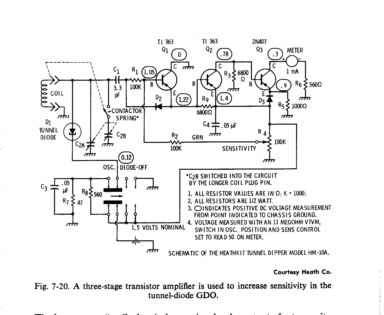
| Jeff Liebermann <jeffl@cruzio.com>: Nov 30 05:05PM -0800 On Mon, 30 Nov 2015 19:05:02 -0500, Michael Black <et472@ncf.ca> wrote: >It seemed like the Tunnel Diode got a lot of press in the sixties in the >hobby magazines, but much of it wsa novelty. For good reason. Tunnel diodes flew in most of the early satellites up to about 1990 because it was the only reliable microwave device available at the time. >things were shown, that tunnel diode FM broadcast receiver was more unique >becuase of the low IF and pulse counting detector than that it used a >tunnel diode as a mixer/oscillator down to that low IF. I believe you're referring to the HW-10 GDO: <http://tubularelectronics.com/Heath_Manual_Collection/Heath_Manuals_H-HM/HM-10a/> <http://tubularelectronics.com/Heath_Manual_Collection/Heath_Manuals_H-HM/HM-10a/HM-10A.gif> No pulse counting detector but rather a simple half wave RF rectifier followed by 3 stages of DC amplification. As I vaguely recall, I had difficulties getting a clean dip because the tunnel diode was probably oscillating on multiple frequencies at the same time. I may have an HW-10 GDO somewhere in my junk pile. I dropped it from about 60ft up during an antenna raising party. It landed in some bushes and did not appear to be damaged, but failed to function afterwards. I also have a few new TEK tunnel diodes. >those at least took advantage of the device at the time, but the time >passed pretty fast before other things didn't do most of what a tunnel >diode could do. Tektronix also used tunnel diodes in their oscilloscope trigger circuitry: <http://w140.com/tekwiki/wiki/Tunnel_diodes> I use one testing scope rise time: <https://richardsears.wordpress.com/2013/04/27/tunnel-diode-pulser/> GE Tunnel Diode Manual (1961): <http://w140.com/Ge1961TunnelDiodeManual.pdf> Today, Aeroflex/Cobham/Metelics currently sell tunnel diode detectors and use them in their instruments: <http://ams.aeroflex.com/metelics/micro-metelics-prods-TD-MTD.cfm> <http://ams.aeroflex.com/metelics/micro-metelics-prods-TD-MBD.cfm> Sorry, but tunnel diodes are not quite dead and obsolete. >So I think the Heathkit tunnel diode dipper was mostly for novelty sake. Nope. During the 1960's, the big draw for Heathkit was that kits were much cheaper than labor intensive assembled products. Heathkit had to do something to keep the price down on their products. Cheap was the order of the day and tunnel diodes were CHEEEEEEP. -- Jeff Liebermann jeffl@cruzio.com 150 Felker St #D http://www.LearnByDestroying.com Santa Cruz CA 95060 http://802.11junk.com Skype: JeffLiebermann AE6KS 831-336-2558 |
| Phil Hobbs <pcdhSpamMeSenseless@electrooptical.net>: Nov 30 08:44PM -0500 On 11/30/2015 08:05 PM, Jeff Liebermann wrote: >> used a tunnel diode as a mixer/oscillator down to that low IF. > I believe you're referring to the HW-10 GDO: > <http://tubularelectronics.com/Heath_Manual_Collection/Heath_Manuals_H-HM/HM-10a/> <http://tubularelectronics.com/Heath_Manual_Collection/Heath_Manuals_H-HM/HM-10a/HM-10A.gif> > were much cheaper than labor intensive assembled products. Heathkit > had to do something to keep the price down on their products. Cheap > was the order of the day and tunnel diodes were CHEEEEEEP. I've never used one, but I suspect that part of the reason that tunnel diode dippers are inferior is that you can't run a high-Z tank without tapping the TD way way down, so that you need an impractically large split variable capacitor. Nuvistors are really good for that, over a pretty wide frequency range. Cheers Phil Hobbs -- Dr Philip C D Hobbs Principal Consultant ElectroOptical Innovations LLC Optics, Electro-optics, Photonics, Analog Electronics 160 North State Road #203 Briarcliff Manor NY 10510 hobbs at electrooptical dot net http://electrooptical.net |
| DJ Delorie <dj@delorie.com>: Nov 30 03:19PM -0500 > Show me the phase difference between your "TRUE" 2 phase and the > "FALSE" 2 phase that you seem to know so much about. Ah, this old argument... I put some graphs at [1] that show the differences using non-sine waveforms. Stepper motors use 2 phase power. The zero crossings occur at different points in time to give the motor a "rotating" power profile. Houses use single phase power with a central tap. It's no different than having a power transformer for your project that provided 5, 15, and 24 VAC via different taps. A house transformer provides 120 and 240 VAC via taps. We typically tie the central 120vac tap to neutral, providing -120 and +120 taps instead. This is no different than tying your project's 5v tap to "ground", providing -5, +10, and +19 vac taps. One way to "prove" the difference: look for upstream noise on the power line. With two phase power, the other power line should have the same noise 90 degrees later (or not at all). In single phase power, the other power line has the same noise but negated. I.e. houses have two 120VAC taps which differ in magnitude (or polarity, +120 vs -120), not phase. Like batteries, you can use one tap for 120v or use both in series to get 240v. Another way is to look at my driveway, which only has one power line coming from the road (plus a ground) (I have my own transformer). If I had two phase power, I'd need at least two (originally 2 phase used four, which is why three phase won out - fewer wires) power lines. [1] http://www.delorie.com/electronics/split-phase-vs-two-phase.html https://en.wikipedia.org/wiki/Single-phase_electric_power https://en.wikipedia.org/wiki/Two-phase_electric_power https://en.wikipedia.org/wiki/Three-phase_electric_power |
| "Tom Del Rosso" <fizzbintuesday@that-google-mail-domain.com>: Nov 30 02:00PM -0500 Phil Allison wrote: > hence lower ESR values compared to the same size caps made in the > past and so can handle higher operating currents without excessive > self heating. What time frame do you mean by "modern" as opposed to "past?" When motherboard caps fail long after the "plague" was over, is it mainly due to the voltage being under-rated? -- |
| You received this digest because you're subscribed to updates for this group. You can change your settings on the group membership page. To unsubscribe from this group and stop receiving emails from it send an email to sci.electronics.repair+unsubscribe@googlegroups.com. |
No Response to "Digest for sci.electronics.repair@googlegroups.com - 25 updates in 6 topics"
Post a Comment