- Roomba lawn mower - 2 Updates
- Fan problem - 5 Updates
- Powering up old stuff that's not been run for several years - 1 Update
- Speed control adjustment causes drill motor to stop - 1 Update
- Harman Kardan AVR1700 Rcvr BCO update - 1 Update
- OTA TV reception problems - 7 Updates
- Replacement laptop ps connection ? - 1 Update
- Need help diagnosing laser printer - 1 Update
| avagadro7@gmail.com: Nov 08 06:22AM -0800 On Wednesday, November 2, 2016 at 11:50:31 AM UTC-4, (PeteCresswell) wrote: > neighbor's cat or dog - but virtually no deer. > -- > Pete Cresswell What brand type light sensor did you use ? estimates on sensor range....movement activation...effective target area ? I lived above a waterfall in black bear country. The fall thundered n vibrated ground fall winter spring. Naybors had serious bear problems. Not in the falls area despite using a bottle landfill against the buildings north wall. Added a Wolo motorcycle air horn to my van under hood lip...horn attached to hood. Horn freezes deer elk onto roadside. With the OEM horn operating. |
| "pfjw@aol.com" <pfjw@aol.com>: Nov 08 07:08AM -0800 On Saturday, November 5, 2016 at 6:54:31 PM UTC-4, Michael Terrell wrote: > They don't get mad. > They don't get even. > They go for over unity! ;-) True enough. Deer are rather stupid and might actually be afraid of Hillary. Whereas a Trump mask would definitely attract them - also any sheep, goats, rabbits and other herd animals in the area. Certainly any such unwilling or unable to think for themselves. Peter Wieck Melrose Park, PA I am not a member of any organized political party. I am a Democrat. Will Rogers Vote Early and Vote Often. Alphonse Gabriel Capone |
| N_Cook <diverse@tcp.co.uk>: Nov 08 12:21PM Regular 2 wire 12V , 0.14A brushless fan. At some point in its history something has been rubbing against the interior part of the impellor. Not these days, perhaps dislodged and blown out through the grill. Black plastic impellor with whitish cicular streaks, the body of the impellor is black throughout , so distressed plastic going white, like flexing a bit of black plastic and goes white at the stressing, not white paint or such. Anyway that or just normal aging/grime etc it now makes a nasty bearing noise when warm , so I replaced it. This is a Mark Bass amp with low speed start and on-demand speeding up circuit. I replaced it with 12V 2A and that was sufficient to (presumably) overload the 18V, or so, line off the SMPS and amp goes into protect. Not even a slight kick of the impellor Tried the original again, and that is fine. Tried a 12V ,.15A one and again protect mode, same sort of start up current draw as the original, but goes into protect. Tried a 12V ,0.08A half size one and that is ok. A resistor in the fan control circuit should be 150R and is now 176R , so something obviously wrong there, something also wrong in the ps as well, if it can drop out just from increase of load by 0.01 amp , something is awry surely. Something special/odd about Chinese XinFans ? The fan drive starts in slow speed mode, no confirmation full speed for 2 seconds at startup, which I like to see on such amps , but I don't think is built-in to these amps |
| N_Cook <diverse@tcp.co.uk>: Nov 08 12:27PM On 08/11/2016 12:21, N_Cook wrote: --> 12V 0.2A |
| "pfjw@aol.com" <pfjw@aol.com>: Nov 08 05:29AM -0800 On Tuesday, November 8, 2016 at 7:21:17 AM UTC-5, N_Cook wrote: >> Much Snippage << Questions: a) What is the actual resistance in ohms of the OEM fan and the replacement fan if measured across the contacts. b) Have you changed the bad resistor yet? If not why not? c) Same question of measured resistance on the lower current fan that does not trip into protection mode? Suggestions: a) Replace all the out-of-spec resistors with correct replacements. Think long and hard before upping the wattage if there is any chance that the resistor may also act as a fuse under extreme conditions. b) Perhaps a small thermistor on the fan line might reduce the overload trip - meaning that what the fan pulls running may be much less than what it takes to start it. |
| N_Cook <diverse@tcp.co.uk>: Nov 08 02:19PM > Suggestions: > a) Replace all the out-of-spec resistors with correct replacements. Think long and hard before upping the wattage if there is any chance that the resistor may also act as a fuse under extreme conditions. > b) Perhaps a small thermistor on the fan line might reduce the overload trip - meaning that what the fan pulls running may be much less than what it takes to start it. Interesting but I don't know what it tells me, a VDR or some thyristor cct, start-up hold-off, in the working ones? Working .08 and OEM .14A ones higher than 10M DVM-R 0.15A 19.3K , DVM-R and .2A 19.9K I'll recheck but i think the fan comes on when the relay clicks over, so not as though the fan is kept out of circuit when the SMPS first starts up. Even then a pretty light load, even in the sense of start-up current, or could that current be an amp or more for a mS or so |
| "pfjw@aol.com" <pfjw@aol.com>: Nov 08 07:03AM -0800 On Tuesday, November 8, 2016 at 9:19:47 AM UTC-5, N_Cook wrote: > not as though the fan is kept out of circuit when the SMPS first starts > up. Even then a pretty light load, even in the sense of start-up > current, or could that current be an amp or more for a mS or so Sheesh, Guy!! 10Meg vs. 20K +/- and you are not sure what it is telling you? The system is seeing the non-working fans as, relatively, a dead short. No wonder it goes into instant 'protect mode'. You need a replacement fan with a internal resistance in the 8 - 12 meg range. Peter Wieck Melrose Park, PA |
| "pfjw@aol.com" <pfjw@aol.com>: Nov 08 06:00AM -0800 I took my 48 hour rule before replying - hip-shots often ricochet. > What you said, or reranted is not wrong in some instances. One notable exception is audio amps that use VFETS for outputs, which are depletion mode and WILL fry if you try to run the up slow on a variac, at least in the Sony ones. I don't know of any others but to be tolerant of low AC input it would take a quite special design with abnormal conditions in mind. I worked for a Sony Signature dealer and ASC back before their product turned to real shit and I can tell you that i n most cases, abnormal conditions were not on their engineers' minds. Consider that statement - it suggests that a brown-out would fry the equipment. Brownouts are quite common in certain regions of the US (sadly) and though rare in our particular case, we are on a double-fed distribution line as there are neighbors with mains-powered life-support equipment nearby. What will happen under extreme storm conditions (twice in 8 years) is that one end of the line may short due to a tree fall or similar, and draw available current (and voltage) way down. Hell on motor-based equipment such as refrigerators or freezers and some electronics. But, we have suffered no failures as a result. Yes, the critical 'stuff' is on surge protectors, but the point is that consumer equipment should be somewhat resilient and designed for real-world occurrences. I have to ask, have you personally observed such a failure due to such a cause? > Dim bulbs and variacs come in handy when you have repaired most regular solid state amplifiers. Once you drop $35 worth of silicon in them for a fried channel it is nice not to have all that short out in the first millisecond. > With most tube stuff, honestly I would just plug it in. Possible exceptions would be if it has selenium rectifiers. Even moreso a high end tube amp with a big old 5U4 but using a selenium rectifier for the negative bias to the outputs. And a dead-shorted filter cap would do *WHAT* in ten seconds? Or a shorted rectifier tube? How much current for how long to wipe out an output transformer? Remind me not to send you any of my vintage equipment for repairs... > Bottom line is you can't just make a blanket statement about working on all equipment. And with the advent of the SMPS, there are even less assumptions that can be made. You can usually use a DBT on like a DVD player or something like that and it will keep the smoke in in most cases. But the normal current drain is usually so low all a hundred watt bulb will do is keep you from burning foil off the PS board. Some short on the five volt line is not protected and if it is going to fry something it is going to succeed. Then, if you use a lower wattage bulb, some SMPSes won't start. I am not so sure that the OP was concerned about equipment made after the year 2000, and/or equipment that has been sitting on a shelf for six months. I believe the thrust was towards equipment that has been sitting in a barn, cellar, shelf or garage for 20 - 60 years. Nor would I spend that much time on a consumer commodity, the repairing of which would likely cost more than a new one - were it even possible. > Before I got kicked off AK they were always talking about the DBT. And really it does prevent pretty much all board burning. You burn the foil of a circuit board it is not fun to fix, especially with audiophiles who are going to want your repair to follow the same path as the original foil. I have done that type of rework but really most of the shit today does just fine with jumper wires. Getting kicked off AK is not difficult. Probably speaks well of you that you were. As to Dim Bulb Testers - they have their (very limited) uses as something of a protective device. They will reduce immediate damage (those first 15 seconds) but they are NOT suitable as a final indicator. > Lately I am dealing with a design defect in amps built by Apex for RSQ, KDS and Technical Pro. All a bunch of liars on the power specs, Technical Pro claims like 1,300 watts or something on an amp that actually puts out about 90 watts a channel. The defect is that the assholes thought the bias regulator would just hold itself to the heatsink. Well they don't, and now ater going through several options we just could not make happen I am simply gluing them. Got me some JB Weld and made some clamps out of a couple of coat hangars. How is that for factory service ? You well know that equipment is built down to the price/purchase point. Where it is perfectly possible, even today, to purchase 'good stuff' at a decent price, the research required to do so is considerable. This applies to anything from appliances to shoes or toys. > Enough rant, back to the subject. The DBT and variac have actually lost some of their usefulness. They are not useless but it does depend on what you are working on. Old tube stuff I would just plug in. For a few seconds. then I would remove all the tubes ad plug it in for longer. then I would put in the rectifier tube and see what happens to the current draw, with all the other tubes out. Scope the caps, if all the other tubes are not in there and you got ripple you got a problem. Turn if off before you blow that 5U4, which is no longer available for $3. The shipping is more than $3. *NOTHING*, repeat, nothing 'just gets plugged in' on my bench. Even if I am not doing the 'variac' thing for modern solid-state stuff, I will pre-set the voltage at 118V and then turn on the item to watch how much current it draws. Anything with a tube gets the full treatment. > I have had a pretty diverse career and even got a little bit into CNC machines but not much. I learned automotive electronics when they started with those ECMs and shit. We flipped cars, and the reason we made money was because the backyard mechanics could not understand electronic and My Goodwrench forgot there was an actual engine under all that shit. I beat them several times in troubleshooting. Three of them making fifty bucks an hour looking at a computer readout and can't tell you have a burnt valve or a fouled plug. And the idiots probably made more money than me. > If you think powering up old electronics is scary, try starting an old car that has been sitting for 20 years or more. That's why some people actually take them apart first. A 1968 VW beetle in 1992, the car had not run since 1970. a) Drain oil. b) Mix one quart 30W oil with one gallon kerosene. c) Pour into crankcase. d) Remove spark plugs. e) Squirt an ounce of Marvel Mystery Oil into each cylinder. f) Turn driveshaft by hand ten full turns. g) Drain kero mixture. h) Allow to sit overnight. i) Re-squirt MMO. j) Turn ten times again. k) Add correct amount of 30W oil. l) Install new spark-plugs. m) Points-condenser-rotor-cap-wires Start. Run at idle for 15 full minutes. Gradually run up to 2,000 rpm, hold at 2,000 rpm for 10 minutes. Check for any oil leaks - and there will be some! Run for one hour, varying rpm from idle to 3,500. It also works on water-cooled engines - I did roughly the same thing to a Mercedes 220 back in the day with good results. > Well not completely apart but they will do a compression check, change the oil, whatever they can coax out of the crankcase that is and put new oil in it, drain the gas tank, pressure check the cooling system maybe, but that can come later after the thing actually starts. I cannot imagine doing a compression check on an engine that has sat idle for even a year without bad results - scored cylinders at the least. That is the point of the MMO and hand-turning. > Everything requires a slightly different approach. Surely. But first principles do apply. Peter Wieck Melrose Park, PA |
| Tim R <timothy42b@aol.com>: Nov 08 05:16AM -0800 I have one of those small bench top drill presses. It stopped starting a while back. So I figured it's probably all gunked up inside and just needed a good cleaning and lube, at least it's worth a shot. Nope, I got the case open and everything looks good. Turned it on, it started fine. It has an adjustable speed dial, it was set on medium. I touched it and it quit and wouldn't restart. The drill will start with the speed dial at medium or high but not in between, and stops instantly if the speed control is moved when it's running. I expected you could use a speed control to ramp it up and down while it's running but this one doesn't function that way. Is it broken, or are they supposed to do that? |
| svaeiou@gmail.com: Nov 08 02:50AM -0800 On Friday, July 5, 2013 at 2:30:28 PM UTC-5, root wrote: > There is nothing in the user manual about this problem. > Any help? > TIA I had this happen to me yesterday and tried the last method mentioned, flipping the power switch in the back then unplugging the power cord, then plugging it back in, flipping the power switch back on and holding the surround sound button in for 5 seconds, and.........IT WORKED!!! Thanks so much for the help!! |
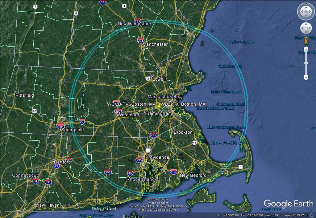
| Jeff Liebermann <jeffl@cruzio.com>: Nov 07 09:09AM -0800 On Sun, 6 Nov 2016 16:40:35 -0800 (PST), captainvideo462009@gmail.com wrote: >with channel four. While most other channels are presently >operating fine, for the past 10 days or so channel 4's signal >has been in the toilet. The signal varies in strength and quality, you could be dealing with knife edge diffraction off of towers, hills, and buildings along the line of sight. At 60 miles, you're almost certain to have a potential problem with Fresnel zone diffraction. <http://www.proxim.com/products/knowledge-center/calculations/calculations-fresnel-clearance-zone> I can generate a path profile to see if there are any obvious problems, but I need to know the lat-long of your location and elevation of your antenna. Here's a sample output: <http://802.11junk.com/jeffl/coverage/RST/> >WCVB, operates on UHF channel 20, runs 625 KW, and shares the >same tower and has it's antenna at the same height as channel 4's, >and we never have any problems with that channel. <https://transition.fcc.gov/fcc-bin/tvq?call=WBZ> <https://transition.fcc.gov/fcc-bin/tvq?call=WCVB> The antennas appear to be almost identical. I just checked the FCC 41dBu service contours for both stations and they are identical. <http://802.11junk.com/jeffl/coverage/KBCZ-WBZ/KVCB-WBZ.jpg> Transmit power difference isn't going to do much. By all reason and logic, the signal strengths should be identical assuming the path is clear of obstructions. Note that the 41dBu contours do NOT represent the actual coverage pattern of the stations. The FCC calculations are based on the assumption that the earth is flat and lacks mountains and hills. These coverage maps should be better: <http://www.tvfool.com/index.php?option=com_content&task=view&id=15&Itemid=1> You might try checking what might be expected at your location in the way of TV reception: <http://www.tvfool.com> Check the calculated signal strengths and see if it's even theoretically possible to receive either station at your unspecified location. >Could propagation be that much different 60 MHZ apart? What >is really weird is that the signal just drops to almost nothing. Yes, due to frequency selective fading. What happens is that you may have two paths between the TV station and your receiving antenna. If the reflected path is some odd numbered multiple of 1/2 wavelength, the signals will cancel. At about 500 MHz, 1/2 wavelength is about 1ft. Move your antenna 1ft in any direction and see if it makes any difference. >I discussed this with the chief engineer at Channel four and >he had no explanation for this. Does anyone have any theories >about this? Thanks, Lenny Oh, lots of theories. For example, a broken TV tuner that has a problem on some channels. Some kind of OTA TV amplifier with an uneven frequency response. Badly terminated or connected TV coax cable causing a notch at one frequency. TV antenna with a broken element causing a notch at one frequency. Local source of interference on one TV channel, but not the other. It might be that one TV station is having transmitter or antenna problems. I could probably conjure a few others. The easiest way to troubleshoot this is by substitution. Start with a different antenna connected directly to the TV with a different coaxial cable. It will probably not be as good as a rooftop antenna, but it should hear something. Compare the signal levels of the two stations. If they're the same, you're problem is somewhere in the antenna, amp, or coax feed system. If they're still different, it might be the TV. Try a different TV. Good luck. -- Jeff Liebermann jeffl@cruzio.com 150 Felker St #D http://www.LearnByDestroying.com Santa Cruz CA 95060 http://802.11junk.com Skype: JeffLiebermann AE6KS 831-336-2558 |
| Fred McKenzie <fmmck@aol.com>: Nov 07 12:59PM -0500 In article <2650dcca-df6a-48eb-abd0-32aae53fc90d@googlegroups.com>, > almost nothing. > I discussed this with the chief engineer at Channel four and he had no > explanation for this. Does anyone have any theories about this? Thanks, Lenny Lenny- If you provide data to Jeff, he can give you a more accurate prediction of how well you should receive the station. As a rough estimate, the range of an signal in miles is the square root of twice the sum of transmitting and receiving antenna heights in feet. For 60 miles, the sum of heights would be 1800 Feet. As others mentioned, reflections can make a difference. Was a large building erected about the time you noticed the reduction in signal? Fred |
| captainvideo462009@gmail.com: Nov 07 10:54AM -0800 |
| dplatt@coop.radagast.org (Dave Platt): Nov 07 11:21AM -0800 >What is really weird is that the signal just drops to almost nothing. >I discussed this with the chief engineer at Channel four and he had no explanation for this. Does >anyone have any theories about this? Thanks, Lenny That sounds as if you may have a multipath situation. The signal from the transmitters is reaching your receive antenna via two different paths - e.g. once directly, and once after reflection off of a building or mountain or ???. If the two different paths deliver signals that happen to be of nearly equal strength, and nearly 180 degrees out of phase with one another, they will largely cancel out when they are combined by your antenna, and the signal strength will take a huge dive. Because the effective length of the signal paths (measured in wavelengths) is a function of the frequency, it's entirely possible for two different channels transmitted from the same tower to behave very differently. Even a small frequency difference can shift the difference-in-path-length by 180 degrees. 60 MHz difference is far more than enough for this effect to show up. Other possibilities: - Somebody may have put up some sort of structure which happens to resonate at the UHF Channel 30 frequency, thus creating a frequency-selective reflector. - It's possible that another station is now operating on Channel 30, somewhere within antenna range of you, and its signal is now interfering with WBZ. This might indicate that a new station has gone on-line (or an existing one has changed frequencies) or might indicate that there's some tropospheric ducting or other form of "skip" bringing an out-of-area station's signal to you. - There might be some form of local interference - a spurious transmission on or near the Channel 30 frequency. https://www.fcc.gov/media/television/tv-query can be used to find stations on specific frequencies. You could plug in your location and get a list of all stations (or those on channel 30) within a specific radius of your location. |
| Jeff Liebermann <jeffl@cruzio.com>: Nov 07 11:32AM -0800 On Mon, 07 Nov 2016 09:09:26 -0800, Jeff Liebermann <jeffl@cruzio.com> wrote: ><https://transition.fcc.gov/fcc-bin/tvq?call=WBZ> ><https://transition.fcc.gov/fcc-bin/tvq?call=WCVB> Coverage maps of WBZ and WCVB. Please note that WBZ has or had a transmit power upgrade application pending with the FCC to increase their output to 941kW. I'm not sure if the coverage map is for 825kW or 941kW. <http://802.11junk.com/jeffl/coverage/KBCZ-WBZ/WBZ-coverage.jpg> <http://802.11junk.com/jeffl/coverage/KBCZ-WBZ/WCVB-coverage.jpg> Both coverage maps look fairly close. However, at 60 miles you're well outside the "normal" coverage area. I'm wondering why WCVB works at 60 miles. What do you have for an antenna and amp at your end? I'm otto time for this today. More tomorrow. -- Jeff Liebermann jeffl@cruzio.com 150 Felker St #D http://www.LearnByDestroying.com Santa Cruz CA 95060 http://802.11junk.com Skype: JeffLiebermann AE6KS 831-336-2558 |
| Jon Elson <jmelson@wustl.edu>: Nov 07 02:35PM -0600 > I discussed this with the chief engineer at Channel four and he had no > explanation for this. Does anyone have any theories about this? Thanks, > Lenny Anybody hit or knock down a pole in the area? I assume your neighborhood is wired for cable. Damage to poles can knock connectors partially loose, allowing a LOT of signal to flow onto the outer sheath. Could be a signal right on the same frequency as Chan 4. I remember a LONG time ago, we had a lightning storm, and someone in the area reported TV interference (back in the analog days, you could easily tell it was interference) . Turned out the lightning had blown out the output filters on a two-way radio base station, so it was radiating at the drive frequency. Could be something similar, a radio transmitter emitting unwanted frequencies. I've even heard of rusty fences and the like developing rectifiying junctions that were mixing various broadcast frequencies and blotting out one particular channel. Are the others with the same problem very close to you, or some distance away? If very close, then likely it is a very local interference source, might be VERY weak, and darned hard to find. If they are miles away, then it is a larger source, and maybe something the station might be willing to send a guy out with a field intensity meter to see if he can find where it is coming from. Hmmm, anybody put up a big building nearby? Some of these glass towers can become excellent near-microwave reflectors, and might be bouncing signals from some other area toward your location. Could also be a wireless security system, baby monitor, wireless cameras, or some other gear of that sort that is out of adjustment. Jon |
| whit3rd <whit3rd@gmail.com>: Nov 07 10:05PM -0800 > ... for the past 10 days or so channel 4's signal has been in the toilet. This station, WBZ TV operates on UHF channel 30, runs 825KW, and has an antenna height of 390 meters. By contrast Channel 5, WCVB, operates on UHF channel 20, runs 625 KW, and shares the same tower and has it's antenna at the same height as channel 4's, and we never have any problems with that channel. Could propagation be that much different 60 MHZ apart? What is really weird is that the signal just drops to almost nothing. If there's a nearby signal to "channel 30", it could be saturating your input amplifier. It's counterintuitive, but try a passive attenuator and see if it improves your reception. The attenuator has to be between the antenna and the FIRST amplifier for the RF signal, so if you have a mast-mounted preamp, that's a problem. Saturation can happen in an RF input amplifier, reducing the signal gain, due to an off-frequency signal that is completely filtered out in later stages. I'm not sure if your signal indication would read the spurious signal or not. If this is a longterm problem, the best solution is an RF trap tuned for the too-strong signal. That won't hurt your signal strength for the other channel, like an attenuator does. <http://www.mcmelectronics.com/browse/Attenuators/0000000801> |
| Jon Elson <jmelson@wustl.edu>: Nov 07 02:51PM -0600 N_Cook wrote: > cannot think of anything off the shelf. Using a pair of Q or Trident > type sockets and pins, offset axially , to give the polarisation. > Cosmetic appearance does not matter. How about gluing a modified USB connector on the outside of the laptop? Cut the plastic connector inside so a standard USB can't mate to the modified connector? Like have a bar across the middle to block the standard type. Jon |
| Jon Elson <jmelson@wustl.edu>: Nov 07 02:48PM -0600 mike wrote: > but I have a long history of using one good system to try to fix > a bad one and ending up with two bad ones. With those sorts of voltages running around, any kind of probing carries a LOT of risks! So, you are wise. > I had cleaned the contacts and swapped cartridges dozens of time. > Now, it's all good! I didn't actually fix anything, so I'm expecting > it to fail again. Well, you did mention a big toner spill. That stuff is conductive, and so you have to get it nearly all cleaned up, or it will get in somewhere and load down a corona supply. I'm guessing somewhere along the trail you cleaned off the magic spot where the toner had shorted something out. > shown in the picture could possibly happen. I can't come up with > a failure mode that would produce such a varied banding pattern > on successive printouts of the same page. Well, a weak corona voltage or dirty corona wire could give poor charge, so the toner didn't all transfer to the paper. Then, the weak wiper blade didn't clean the drum, so the toner accumulated as it rotated. But, I'm just guessing. My experience has mostly been with the bad wiper blades. Once the drum is covered in toner, the laser beam can't write the pattern of charged and discharged areas, so the whole page comes out grey. But, you may have actually had TWO problems going on at the same time, much harder to diagnose. Jon |
| You received this digest because you're subscribed to updates for this group. You can change your settings on the group membership page. To unsubscribe from this group and stop receiving emails from it send an email to sci.electronics.repair+unsubscribe@googlegroups.com. |
1 Response to Digest for sci.electronics.repair@googlegroups.com - 19 updates in 8 topics
YoBit lets you to claim FREE COINS from over 100 unique crypto-currencies, you complete a captcha once and claim as many as coins you need from the available offers.
After you make about 20-30 claims, you complete the captcha and keep claiming.
You can click CLAIM as much as 30 times per one captcha.
The coins will stored in your account, and you can exchange them to Bitcoins or USD.
Post a Comment