- Using magnets with tiny SMD devices - any electronic concerns? - 1 Update
- Blank RF Probe tips - 2 Updates
- Ground is no longer at ground potential - 6 Updates
- Florescent light fixture gone bad - 1 Update
- Another EPROM question. - 5 Updates
- Old EPROM questions - 9 Updates
- 20,000 Watt, 5000 Lb Stereo Amplifier (Only $50,000). - 1 Update
| "Michael A. Terrell" <mike.terrell@earthlink.net>: Apr 01 12:02PM -0400 > Good to raise the question - which deserves an answer that addresses it directly. > Magnetic fields are largely dissipated when bridged. Which is why horseshoe magnets, as one obvious example are bridged when shipped. A bar between N & S., that is. DO try this at home. Take the typical cartoon-type horseshoe magnet and iron filings (in a bag for the purposes of neatness). With the bar and without the bar. > When a magnetic parts-picker is holding its part, it is bridged. The electromotive coil is sitting between the two poles which are gapped at the proper size to pick up the part in question. The part-in-place dissipates extraneous fields, is demagnetized by the shifting field applied to it, and when the system shuts off (dropping the part) also absorbs and dissipates the transient - which ain't much nohow, anyway. The tools to pick up SMD components use vacuum. Both manual, and Pick-N-Place machines. -- Never piss off an Engineer! They don't get mad. They don't get even. They go for over unity! ;-) |
| bruce2bowser@gmail.com: Mar 31 10:41AM -0700 MJC wrote: > In article <46vmdcdgb2qu79l64s5cf9uobdrdbuj34g@4ax.com>, olds...@tubes.com says... >> germanium, but it is rare and thus costly so they changed to silicone. > Definitely silicon, not silicone. In chemistry, one letter makes a big > difference! There's silica, silly and silly puddy, too. |
| "Michael A. Terrell" <mike.terrell@earthlink.net>: Apr 01 11:49AM -0400 Foxs Mercantile wrote: > <http://www.ebay.com/itm/132140338092> That was sold. Here is a Heathkit probe: http://www.ebay.com/itm/382023629649 Vintage-HEATH-Schlumberger-RF-PROBE-Model-PKW-3A-w-MANUAL-309-C/ Some of the old construction projects used aluminum cigar tubes, which can be found on Ebay. I use a Boonton 9200 Digital RF millivoltmeter. The probe has a pair of diode, which are fed into a chopper circuit. It is good, past 800 MHz and it has a very low input capacitance. A divide by 100 capacitive divider/attenuator is also available. I have a couple of the older Boonton 92 series analog meters, as well -- Never piss off an Engineer! They don't get mad. They don't get even. They go for over unity! ;-) |
| oldschool@tubes.com: Apr 01 09:32AM -0500 Scientists have determined that ground is no longer at ground potential. It dont matter if you're referring to the ground for your home's electrical system, or the chassis ground in an electronic device. Due to changes in the earth's structure, caused by both natural causes, such as shifting of the earth's plates, and man made deviations of the earth caused by excessive pumping of oil, over use of electronic devices, and the use of nuclear reactors. The earth has changed in structure, and is affecting all of us. Because of this, a Ground is no longer "TRUE GROUND". Anything and everything that is grounded is now roughly at positive 8.243 volts. Thus, everything which is grounded is really not grounded, and living creatures are now all exposed to this roughly +8 volt potential. This may not seem like much, but it accumulates over time, affecting the moods and bodily functions of all living things. Over time it causes illness, mental disturbances, and possibly even cancer and heart disease. Scientists have been investigating this for years, and have noticed a slight upward drift of positive voltage increasing every year. The U.S. government is finally taking action, and other world governments are now considering taking action to bring "ground" back to TRUE ground potential. To achive true ground, heavy copper rods must be driven deeply into the earth's core, but must be insulated from the top 600 feet of soil and rock. This ground potential must then be "piped" to homes and businesses all around the country and abroad. This is a very costly procedure, and in order to bring all of our structures as well as out electronics back to "true ground potential", everyone must connect all electrical systems to these "master grounds", which will be placed at approximately 100 locations around the U.S. (presently two in each State). These grounds will then be wired into our homes and businesses through an extensive grid of heavy gauge wires. Every community will be responsible to distribute this ground to individual structures. Because of the high costs involved, every American will be billed for this service, which will soon be mandatory according to the "National Electric Code". This bill must be paid monthly, just like any other utility bill, and will be based on usage. Thus, the more electrical and electronic devices you have, the more you will pay. Your usage will be determined by using a "ground meter", not unlike your home's electrical meter. It's been planned that by the year 2020, every structure in the U.S. will be connected, and will bring us back to true ground potential. However, other countries must also establish a similar system, or else there may be extensive corrosive reaction of lands not connected, which will occur where the salt water of oceans is at a different ground potential. With an unbalanced ground, the salt water in the oceans may become like giant batteries and thus will eat away at shoreline land and could even cause massive boils, as the ocean waters begin to boil from the heat caused at the center of the oceans, which will also cause massive kills of fish and other ocean life. Therefore, all continents on earth must cooperate and establish systems which will bring the entire planet's electrical systems back to true ground potential. This must be enacted immediately, or in less than one half of a century all living creatures on earth will become so electrically charged that we will all face death due to electrical imbalances in our bodies whenever we have any direct contact with the earth. Act now, encourage your local and national governments to take immediate action to design and built the systems needed to solve this most critical problem. If we do nothing, it will only be a few decades before human and animal lives are severely affected, and our present electronics and electrical systems will all fail. Reprinted from: The Electro Scientific Journal |
| Tom Biasi <tombiasi@optonline.net>: Apr 01 11:12AM -0400 > Scientists have determined that ground is no longer at ground potential. snip a bunch of junk>>> > Reprinted from: The Electro Scientific Journal This is what happens from abuse of drugs. The earth now has an 8 volt potential in reference to what? |
| bitrex <bitrex@de.lete.earthlink.net>: Apr 01 11:16AM -0400 > moods and bodily functions of all living things. Over time it causes > illness, mental disturbances, and possibly even cancer and heart > disease. The only logical solution is to cover the entire country in nickel-plated linoleum tile to protect us. We'll call it a "floor." It won't cost taxpayers a dime - we'll send Gaia a bill for it. |
| Phil Hobbs <pcdhSpamMeSenseless@electrooptical.net>: Apr 01 11:22AM -0400 On 04/01/2017 11:12 AM, Tom Biasi wrote: >> Reprinted from: The Electro Scientific Journal > This is what happens from abuse of drugs. > The earth now has an 8 volt potential in reference to what? I think one of Feynman's lectures asks about what the electrostatic potential of the Earth is. The answer is that it's close to zero, since the Earth is immersed in a conducting medium (the solar wind). Cheers Phil Hobbs -- Dr Philip C D Hobbs Principal Consultant ElectroOptical Innovations LLC Optics, Electro-optics, Photonics, Analog Electronics 160 North State Road #203 Briarcliff Manor NY 10510 hobbs at electrooptical dot net http://electrooptical.net |
| Tom Biasi <tombiasi@optonline.net>: Apr 01 11:23AM -0400 On 4/1/2017 11:12 AM, Tom Biasi wrote: >> Reprinted from: The Electro Scientific Journal > This is what happens from abuse of drugs. > The earth now has an 8 volt potential in reference to what? My apologies, I forgot today's date. |
| Ralph Mowery <rmowery28146@earthlink.net>: Apr 01 11:24AM -0400 In article <obofr4$ct6$1@dont-email.me>, tombiasi@optonline.net says... > > Reprinted from: The Electro Scientific Journal > This is what happens from abuse of drugs. > The earth now has an 8 volt potential in reference to what? Referenced to April 1. |
| oldschool@tubes.com: Apr 01 05:43AM -0500 I have a "Lights of America" Florescent fixture (4 ft - 2 bulb shop light). Only one bulb would light. New bulbs did not fix it. Only one side of the fixture worked. (Always the same side). I finally tore it apart. I have repaired and replaced ballasts in a lot of fixtures, but this one is unique. Instead of having one ballast for the entire fixture, this one has thick plastic ends, with one ballast on each end. These ballasts look more like a small transformer or a choke used in power supplies on electronics. Across the wires on each ballast is a capacitor and a resistor. The choke on one end looked ok and that fed the bulb which worked. As soon as I opened the other end, I found the problem. That capacitor literally had a hole in it, and there was black burnt markings around it. The good capacitor is not labeled like a normal cap, so I dont know what value it is. It says K 505J 250. (I am guessing its 250 volt, but I am clueless about the uf value). Either way, I am sure that finding a capacitor that will work, would only be a guess... But I am posting this for another reason. The wires that cross over to the defective side, are joined in the middle of the fixture with a sealed plastic box, which can not be opened. I put my VOM across those wires and there is no reading (on the ohm setting). Is that a fuse, or what? Like I said, I have never seen this type of setup. Every fixture I have ever opened just had straight thru wires, or used wirenuts to join splices. I can only guess that when the cap shorted, it blew the fuses or whatever is in that thing... Have any of you ever seen this type of setup? I'm only asking this because I am curious. I do not intend to buy a new ballast, which would probably cost as much or more than a new fixture. However I may convert this fixture to 4 ft LED replacement bulbs, which means removing all ballasts and directly wiring the sockets to the AC line (only one one end of the bulbs). I was kind of thinking of converting the fixture to LED anyhow, so now I have more reason to do so. |
| etpm@whidbey.com: Mar 31 10:32AM -0700 I would like to read what is in the old EPROMs in my machine. They contain the ladder programming for the machine. I cannot get a copy of this ladder from Miyano, who made the lathe and wrote the ladder. Is there a way to read what is programmed in these EPROMs? I guess I should ask if there is a way I can read what is in them. I know what a ladder looks like and can read one but I don't know if one can be read from a device just by downloading and using a text reader to see what is there. Eric |
| Ralph Mowery <rmowery28146@earthlink.net>: Mar 31 01:35PM -0400 In article <fa4tdc53qq04k2jcpv7992i7lrm46nbcvs@4ax.com>, etpm@whidbey.com says... > from a device just by downloading and using a text reader to see what > is there. > Eric It would be doubtful if you could. The eprom will give a bunch of hexidecimal numbers. You would need a program that could convert that to the ladder. |
| John Robertson <spam@flippers.com>: Mar 31 11:07AM -0700 On 2017/03/31 10:35 AM, Ralph Mowery wrote: > It would be doubtful if you could. The eprom will give a bunch of > hexidecimal numbers. You would need a program that could convert that > to the ladder. Not to mention there is likely CPU operating code which you would need to learn or find a code disassembler. Not for the faint of heart! If there is a service shop like mine in your area and they have classic tools such as a Fluke 9010 or 9100 then they can read the EPROM(s) by simply pulling the CPU and exercising the motherboard under proper power. Probably... John :-#)# -- (Please post followups or tech inquiries to the USENET newsgroup) John's Jukes Ltd. 2343 Main St., Vancouver, BC, Canada V5T 3C9 (604)872-5757 or Fax 872-2010 (Pinballs, Jukes, Video Games) www.flippers.com "Old pinballers never die, they just flip out." |
| etpm@whidbey.com: Mar 31 05:29PM -0700 On Fri, 31 Mar 2017 13:35:54 -0400, Ralph Mowery >It would be doubtful if you could. The eprom will give a bunch of >hexidecimal numbers. You would need a program that could convert that >to the ladder. That's what I thought. Maybe I can get FANUC or MIYANO to read some EPROMs and provide me with a ladder printout if I send the devices to them. Eric |
| etpm@whidbey.com: Mar 31 05:35PM -0700 On Fri, 31 Mar 2017 11:07:16 -0700, John Robertson <spam@flippers.com> wrote: >simply pulling the CPU and exercising the motherboard under proper power. >Probably... >John :-#)# The whole problem is that there is only one company in the Puget Sound area that I could find that can work on my machine. There used to be several but so many shops went out of business because of Boeing boom/bust cycles that CNC services companies also went out of business. And since I'm on an island that makes service calls even harder to get. Eric |
| Phil Hobbs <pcdhSpamMeSenseless@electrooptical.net>: Mar 31 12:53PM -0400 > should try with the ones I really want back ups of. Any advice? > Thanks, > Eric Assuming they're in the usual cheap sockets, I'd probably destroy the sockets with a scalpel and bend the fingers out before removing the EPROMs. In equipment that old, the pins may be corroded, and you don't want one to fall off. Cheers Phil Hobbs (Who has a lab full of top-of-the-line boat anchors. Love 'em.) |
| etpm@whidbey.com: Mar 31 10:26AM -0700 On Fri, 31 Mar 2017 12:53:45 -0400, Phil Hobbs >Cheers >Phil Hobbs >(Who has a lab full of top-of-the-line boat anchors. Love 'em.) I'll check to see if they are stuck. I don't think they will be though because I have worked on even older FANUC controls and they all seem to have been made pretty with pretty good components. I do have some of theat DeOxit5 contact cleaner. Should I spray some on before attempting removal? Eric |
| John Robertson <spam@flippers.com>: Mar 31 11:04AM -0700 > of theat DeOxit5 contact cleaner. Should I spray some on before > attempting removal? > Eric I'd think a spray of DeOxit would not hurt. It is rare for Eproms to corrode though that depends on the storage environment I've pulled thousands over the years from our arcade games from the 70s and 80s and only a few legs had rotted. But those are easy to spot as the pins look black! If the leg is looking rotted consider unsoldering the EPROM socket with the EPROM still installed. Then, leaving the EPROM in the socket, read it in your programmer. Freeing the legs of the socket can be fun, best to use a Pace or similar desoldering tool that allows you to move the leg around while you are sucking the solder out. John :-#)# -- (Please post followups or tech inquiries to the USENET newsgroup) John's Jukes Ltd. 2343 Main St., Vancouver, BC, Canada V5T 3C9 (604)872-5757 or Fax 872-2010 (Pinballs, Jukes, Video Games) www.flippers.com "Old pinballers never die, they just flip out." |
| "tom" <tmiller11147@verizon.net>: Mar 31 02:10PM -0400 <etpm@whidbey.com> wrote in message news:vvusdctkdaru2ar50h4flkeq6ej7ivmg92@4ax.com... > should try with the ones I really want back ups of. Any advice? > Thanks, > Eric Remember that the EPROMS are static sensitive. Use appropriate anti static procedures when working with those chips. Google ESD for more details. |
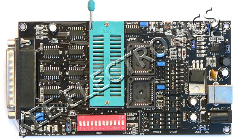
| Jeff Liebermann <jeffl@cruzio.com>: Mar 31 12:32PM -0700 >of theat DeOxit5 contact cleaner. Should I spray some on before >attempting removal? >Eric You're right about Fanuc using decent components. Contact cleaner makes a mess and is not necessary. It something like this Fanuc board? <http://i.ebayimg.com/images/g/66cAAOSwd4tTrwpk/s-l500.jpg> I used to help the owner of a local machine shop maintain a Mori Seiki MV35-35 5 axis machining center, with a Fanuc something controller. For upgrades, I never had a problem removing or inserting the EPROM's. The coolant and oil fog that usually surrounds these machines does a nice job of preventing corrosion. Watch out for the dehumidifier, where condensation might make things rust. Just pry out the EPROMS with a plastic pry tool or "spudger" (to prevent cracking the ceramic EPROM case). Something like these: <http://www.ebay.com/itm/161408350619> Also, take a photograph of the PCB before disassembling so you can put the EPROMs back in the correct socket. For saving the EPROM contents, there are cheap EPROM burners available on eBay. I have one like this: <http://802.11junk.com/jeffl/K6BJ-MSF5000/Willem5.jpg> About $50 on eBay: <http://www.ebay.com/sch/i.html?_nkw=willem+eprom+programmer> However, there are some tricks involved and it's all too easy to make a mistake and trash an EPROM. If you're going to do this yourself, I strongly suggest that you first practice with some junk EPROMs. Good luck. -- Jeff Liebermann jeffl@cruzio.com 150 Felker St #D http://www.LearnByDestroying.com Santa Cruz CA 95060 http://802.11junk.com Skype: JeffLiebermann AE6KS 831-336-2558 |
| etpm@whidbey.com: Mar 31 05:01PM -0700 On Fri, 31 Mar 2017 11:04:32 -0700, John Robertson <spam@flippers.com> wrote: >to use a Pace or similar desoldering tool that allows you to move the >leg around while you are sucking the solder out. >John :-#)# Greetings John, Fortunately the circuit board shows no corrosion. I do have a tool made for removing these chips so I'll just give 'em a squirt. let the stuff work for a bit, and then pull 'em. Eric |
| John Robertson <spam@flippers.com>: Mar 31 05:09PM -0700 > made for removing these chips so I'll just give 'em a squirt. let the > stuff work for a bit, and then pull 'em. > Eric If no signs of corrosion, then I would not spray the board with anything. Take great care that you do not damage traces under the socket when you are prying out the EPROMs. John :-#)# -- (Please post followups or tech inquiries to the USENET newsgroup) John's Jukes Ltd. 2343 Main St., Vancouver, BC, Canada V5T 3C9 (604)872-5757 or Fax 872-2010 (Pinballs, Jukes, Video Games) www.flippers.com "Old pinballers never die, they just flip out." |
| etpm@whidbey.com: Mar 31 05:25PM -0700 On Fri, 31 Mar 2017 12:32:16 -0700, Jeff Liebermann <jeffl@cruzio.com> wrote: >a mistake and trash an EPROM. If you're going to do this yourself, I >strongly suggest that you first practice with some junk EPROMs. >Good luck. Greetings Jeff, The board I am replacing has only 6 EPROMs but still looks similar. Thanks for mentioning picture taking, I will for sure be doing that. I didn't know the programmers were so inexpensive now. Since I have lots of old EPROMs from a few other FANUC controls I am gonna order a reader/programmer and see if I can copy the junk ones. So I'll be asking for advice soon about which programmer to get for my particular devices and how to avoid scrapping them. Thanks, Eric |
| etpm@whidbey.com: Mar 31 05:26PM -0700 On Fri, 31 Mar 2017 14:10:07 -0400, "tom" <tmiller11147@verizon.net> wrote: >Remember that the EPROMS are static sensitive. Use appropriate anti static >procedures when working with those chips. >Google ESD for more details. I will for sure be taking all precautions regarding ESD. Eric |
| bitrex <bitrex@de.lete.earthlink.net>: Mar 31 03:42PM -0400 > * Input power: 230 or 460 vac, 3 phase @ 50 Hz or 60 Hz > * Dimensions: 34" x 44" x 82-1/2"H > $25,000 each I think I remember seeing that same ad on the same store site probably going on ten years ago now. How many of them do they have? Are they still trying to sell the same one? |
| You received this digest because you're subscribed to updates for this group. You can change your settings on the group membership page. To unsubscribe from this group and stop receiving emails from it send an email to sci.electronics.repair+unsubscribe@googlegroups.com. |
No Response to "Digest for sci.electronics.repair@googlegroups.com - 25 updates in 7 topics"
Post a Comment