- Vintage transistors and tin whiskers - 5 Updates
- " Flexible" wire for use in headphones with earcups that swivel? - 2 Updates
- Yamaha dsp-z7 doa - 1 Update
- Weller IG-102 - 1 Update
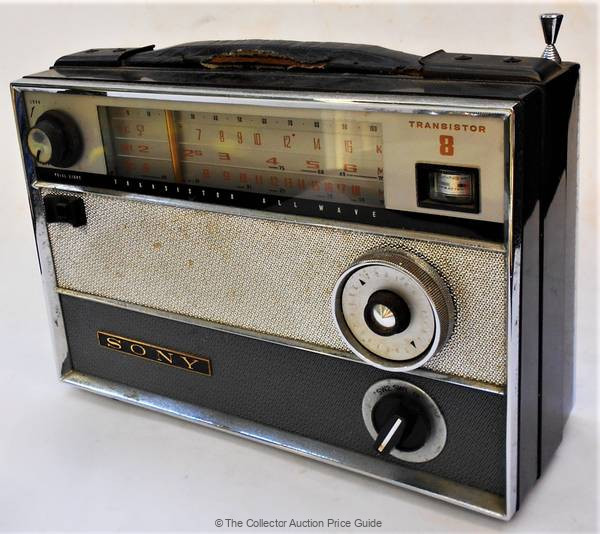
| Pimpom <nobody@nowhere.com>: May 17 10:47PM +0530 On 5/17/2020 10:04 PM, Cursitor Doom wrote: > question is between the case ("screen") and the die and significantly pre- > date the black-painted phototransistors we all fondly recall from 50 > years ago. :-) Ah, sorry. Then those low-ohm figures can't be normal. My dad bought a Sony transistor radio in the early 60s. I remember that it used Japanese Ge transistors like 2SA12, 2SA15 for RF and 2SB75 and 2SB77 for audio. One of my regrets in life is that I never got around to restoring it when he was still alive. This is the model - https://priceguide.thecollector.com.au/wp-content/gallery/auction-928/1960s-Sony-TR-812-allwave-transistor-radio-Sold-for-56-2019.jpg |
| Cursitor Doom <cd@not4mail.com>: May 17 04:34PM On Sun, 17 May 2020 21:06:23 +0530, Pimpom wrote: >> enclosures. > OK, I got the AC188s. With a DMM they measure 25-50 ohms forward and a > few Ks in the reverse direction. I think you've misunderstood the problem here, Pimpom. The leakage in question is between the case ("screen") and the die and significantly pre- date the black-painted phototransistors we all fondly recall from 50 years ago. :-) |
| adrian@poppyrecords.invalid.invalid (Adrian Tuddenham): May 18 12:59PM +0100 > intuitive to me and I'd have thought higher current lower voltage would > be safer for these delicate germanium devices, but WTF do I know? > Is it feasible to remove the whiskers by this sort of method or any other? I have had some success with an Eddystone EB35 by replacing them with silicon transistors and adjusting the base bias to get approximately the same collector current. (I was a tester on the production line at Eddystones when EB35s were going through, so I am the one to blame if they don't meet spec.) -- ~ Adrian Tuddenham ~ (Remove the ".invalid"s and add ".co.uk" to reply) www.poppyrecords.co.uk |
| Michael Terrell <terrell.michael.a@gmail.com>: May 18 05:05AM -0700 On Sunday, May 17, 2020 at 10:15:34 AM UTC-4, Cursitor Doom wrote: > intuitive to me and I'd have thought higher current lower voltage would > be safer for these delicate germanium devices, but WTF do I know? > Is it feasible to remove the whiskers by this sort of method or any other? If the Tin Man in the Wizzard of Oz tried to grow a beard, they would be really big tin whiskers. ;-) |
| abrsvc <dansabrservices@yahoo.com>: May 18 05:43AM -0700 On Sunday, May 17, 2020 at 10:15:34 AM UTC-4, Cursitor Doom wrote: > Is it feasible to remove the whiskers by this sort of method or any other? > Thanks, > CD I have 4 ECG160 transistors (2 that are unused and 2 that look like they may have been used to test something). Send me your address and I'll send them along if you think that these will resolve your problem. I doubt that I will ever use these. Dan |
| Mike S <mscir@yahoo.com>: May 18 01:55AM -0700 I have a pair of Even H3 headphones, the wire that carries power from one earcup circuit board (where the battery and USB connector live) to the other earcup (where the control and sound circuitry live) shorts to ground somewhere in the headband. I can't find parts for this thing so I am going to run my own wire to replace the faulty one. What kind of wire is recommended for this kind of use, where the earcups swivel, tilt, rotate, etc.? I have solid core multi-strand wire I can peel from a ribbon cable, but I'm concerned that the metal will fatigue and break at the bend points. |
| Jeff Layman <jmlayman@invalid.invalid>: May 18 12:21PM +0100 On 18/05/20 09:55, Mike S wrote: > rotate, etc.? I have solid core multi-strand wire I can peel from a > ribbon cable, but I'm concerned that the metal will fatigue and break at > the bend points. Any chance of using the flexible wire from other headphones - even really cheap ones from dollar/euro/pound shops? IME it can be difficult to solder these wires, as trying to strip off the insulation can often break then thin conductor wires, but it will cost very little to give it a try. -- Jeff |
| legg <legg@nospam.magma.ca>: May 13 12:48PM -0400 The ac line relay cycles for 500mS, without display indications. This with or without main TX connected. Housekeeper is live and rises to 13V during the start-up attempt. Power detect line ok. Anyone familiar with start-up sequence of this thing? Looks like you've got to disassemble the whole thing to get at the processor/control area. Is it safe to bypass relay, to run up the power gradually? RL |
| jeff <nomail@example.com>: May 10 03:37PM +0200 > In conclusion- i should deliver vacuum to my IG-102? > Or should i connect compressed air and it makes vacuum > by itself? Does a simple solder sucker not suffice? |
| You received this digest because you're subscribed to updates for this group. You can change your settings on the group membership page. To unsubscribe from this group and stop receiving emails from it send an email to sci.electronics.repair+unsubscribe@googlegroups.com. |
No Response to "Digest for sci.electronics.repair@googlegroups.com - 9 updates in 4 topics"
Post a Comment