- Mark Bass ,CMD 102P, bass amp of 2011 - 2 Updates
- Fluke 8060a meter interconnect strip - 2 Updates
- STUPID QUESTION No. 5 - 3 Updates
- kikisui PAD-L series PSU schematics - 1 Update
- Schmitt trigger problem - 1 Update
| N_Cook <diverse@tcp.co.uk>: May 12 02:56PM +0100 Owner switched on, blue led came on as normal , but between that and 20 seconds grabbing guitar lead, had blown the mains fuse, no input, usual load. No problem in previous use, may be a drop in volume , as for the last month had to use 6 instead of 4 on the volume, but uses different cabs so cannot be certain of that. Both IRFP27N60K ohmic low all round. With trade mark ground off 8pin SMPS supervisor, from combined effort here a few years ago, probably IR2153 ,if like the other flavors of these amps. Any view as to what would cause this sort of failure? and pre-emptive mod around the supervisor circuit? I don't like the great thick slabs of ceramic insulator pads, should be used on bathroom splash-backs IMHO , not heat conductors. The main amps not checked over yet. |
| N_Cook <diverse@tcp.co.uk>: May 12 04:30PM +0100 1 of 3 of each n and p type paralleled audio powerFETs gone ohmic all round, IRFP240 and IRFP9240. So a month ago 1 failed then the other soon after, both failing safe and non-functional? then both going shorted at the last power-up? |
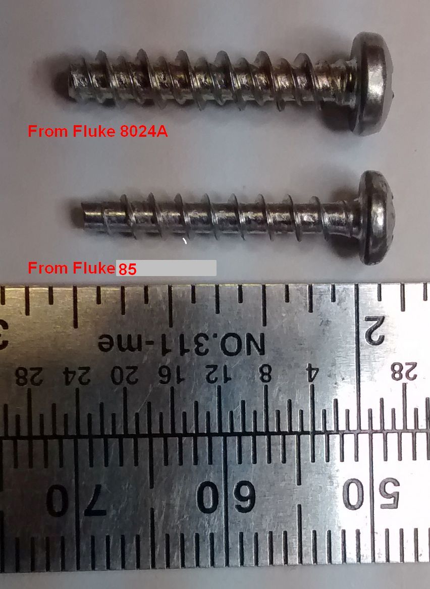
| Jeff Liebermann <jeffl@cruzio.com>: May 11 08:30PM -0700 >8 years ago and I misplaced one of the screws, but if you want the other >two, they're yours. I'm on the east coast so it'll be a week. >John Thanks. Got the screws today. They fit nicely in the 8060A. However, there's a bit of an oddity here. <http://802.11junk.com/jeffl/pics/Fluke%208060a/Fluke-screws.jpg> The Model 85 screws fit in the 8060A, but the original screws (as borrowed from an 8024A) are a bit different. Notice the double spiral, the different pitch, and that the 8024a screw is a bit larger diameter. Which style does your 8060A use? Incidentally, when I removed the 40 pin chip from its socket, I found that some of the socket contacts had gotten wet and started to corrode. I've also got an offset on most scales thanks to leakage across the PCB. Looks like I'll be replacing the socket with something better, and giving the PCB an alcohol rubdown. -- Jeff Liebermann jeffl@cruzio.com 150 Felker St #D http://www.LearnByDestroying.com Santa Cruz CA 95060 http://802.11junk.com Skype: JeffLiebermann AE6KS 831-336-2558 |
| ohger1s@gmail.com: May 12 08:15AM -0700 On Wednesday, May 11, 2016 at 11:30:18 PM UTC-4, Jeff Liebermann wrote: > borrowed from an 8024A) are a bit different. Notice the double > spiral, the different pitch, and that the 8024a screw is a bit larger > diameter. Which style does your 8060A use? The screws from my IBM 8060A are the double helix. The screws I sent you did not actually come from my 85, but from a newer 77. When asking around if anyone had any dead Flukes (trying to locate that p-jfet for my 85), I was given a 77 that was blasted by a microwave oven. The 77 didn't have the jfet I needed so I ended up fixing the 77 and returning it to the donator as a gift, but not before swapping the screws with some generic screws I had as payment :). Those I sent to you because there were three and I only had two from the 85. Whew! > corrode. I've also got an offset on most scales thanks to leakage > across the PCB. Looks like I'll be replacing the socket with > something better, and giving the PCB an alcohol rubdown. When I removed the chip from the socket, I found there was no corrosion evident but two of the tangs in the socket came apart, so I ordered a new socket and put the repair on hold until it arrives. John |
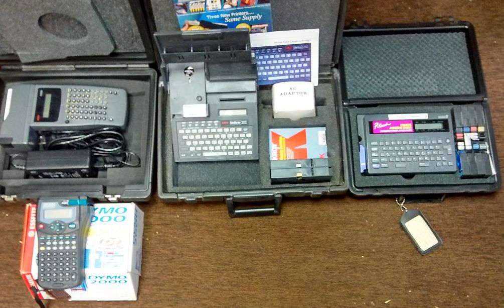
| Jeff Liebermann <jeffl@cruzio.com>: May 11 08:15PM -0700 > Q5 is: how to label wires that is of what material n print substance ? <http://802.11junk.com/jeffl/crud/Label%20Makers.jpg> Make me rich and it's all yours. I had to label what I would guess was about 500 cables at an ISP many years ago. The two Kroy machines will print on shrink tube, which I decided was the easiest and best way. > is there a preferred tape and ink ? All inks fade, rub off, or take too long to dry. What you want are Kroy thermal transfer labels for marking wires. <http://www.kroy.com/thermal/index.htm> > we tried 3M 33 and the felts bought at Wal but the ink fell off ... After the ink falls of, the pressure senitive glue will either melt or evaporate. Then, the black electrical tape will fall off. Same thing happens with most other sticky tapes when they get hot. > masking tape is visually borderline gack .....coating the area with linseed.. Masking tape has the amazing ability to ossify and fall off, leaving the ultimate sticky mess behind on the wire. > any ideas ? Yeah. Since I know you're not going to run out and spend a pile of money on a proper thermal label maker, I have a cheaper trick that I've used with good success. Make your label on a cheap thermal label maker, such as Dymo LetraTag: <http://www.dymo.com/en-US/letratag-plus-lt-100h-silver-label-maker> I have 3 of them, not counting the one's I dropped, threw against a brick wall, or ran over with my Subaru. Make sure you use the plastic labels, not the paper labels. <http://www.dymo.com/en-US/lt-plastic-labels-1-2-in> Print whatever and stick the label on the wire. Then, wrap it with Scotch transparent tape. 3/4" wide if possible. It thinks this is the stuff: <http://www.scotchbrand.com/3M/en_US/scotch-brand/products/catalog/~/Scotch-Transparent-Tape-Refill-Rolls?N=4335+3294529207+3294603591&rt=rud> Not the translucent crap that allegedly looks clear after it's applied, but the stuff that's clear on the roll. I'll check the product name and number next time I visit Office Max. -- Jeff Liebermann jeffl@cruzio.com 150 Felker St #D http://www.LearnByDestroying.com Santa Cruz CA 95060 http://802.11junk.com Skype: JeffLiebermann AE6KS 831-336-2558 |
| avagadro7@gmail.com: May 12 04:46AM -0700 On Tuesday, May 10, 2016 at 4:18:11 PM UTC-4, Tim R wrote: > Some stupid questions are easily googled. Used the term "wire marker." > There are thousands of sites like this: > http://www.cableorganizer.com/cable-identification/ wire markers ! a winner. the Dymo is a surprise.....now what's needed at that price is a transeaver dymo...point n shoot get the wire and local schematic....then press A for the total effective schematic with problem areas. at $35 |
| mjb@signal11.invalid (Mike): May 12 01:44PM +0100 In article <c3s7jblmjis99t8ogcc29mgeloi6no88vm@4ax.com>, >Dymo LetraTag: >Make sure you use the plastic labels, not the paper labels. >Then, wrap it with Scotch transparent tape. Have done all these three. Great little units ... Warning. Some plastic surfaces interact with labels over time. I have some labels where the background has darkened, so instead of black on white, it's black on very dark grey. Weirder, black on yellow has reversed to be dull yellow on brown! This is not a heat issue, the labelling is on the plastic body of 1/4" jack plugs -- is it the plasticisers? And also on a white plastic 4-way socket strip, made of flexible plastic, same darkening. Unaffected on hard/brittle strips in the same location. -- --------------------------------------+------------------------------------ Mike Brown: mjb[-at-]signal11.org.uk | http://www.signal11.org.uk --- news://freenews.netfront.net/ - complaints: news@netfront.net --- |
| legg <legg@nospam.magma.ca>: May 11 10:15PM -0500 kikisui PAD-L series PSU schematics aren't in the normal documentation, but are floating around somewhere. Anyone with a copy they'd care to share. Model PAD55-10L specifically, but the series has basically the same control electronics. RL |
| legg <legg@nospam.magma.ca>: May 11 12:53PM -0500 On Wed, 11 May 2016 10:25:07 -0400 (EDT), bitrex >H when either the START switch S5 or the STOP switch S6 is turned > ON,and goes to L when the switch set to ON is turned > OFF." OK. A confusing description of the switch functions. There is some funny drawing of connections around the footswitch socket J3, so that it's not obvious what plug-free operation is expected. Hardwiring the output of IC3 pin 4 to J3 pin6 would temporarily overstress the IC every time the start switch was pressed. If this connection is expected, then a latching function could be expected of the start switch alone. Q15 is normally saturated. It should turn on shortly after application of power and remain on. (C41 effect) Without the shorted wiring in J3, both start and stop switches should produce a temporary turn-off of Q15, allowing a longish positive-going pulse on it's collector, and a shorter negative-going pulse on normally-off Q16 collector (IC1-R/W). If Q15 is off, with collector high for any length of time, then you would need to check what is preventing it from turning on normally. With the J3 connection, a start button push will latch Q15 low without producing a R/W pulse, and a stop button push will unlatch Q15 to produce a R/W pulse. If that's what you see on the collectors of these two transistors, then there's nothing wrong with this section, if amplitudes and timing are CMOS compatible. You need to scope with high-z x10 scope probes(~10meg z). possible faults R85 hi z Q18 short/leaky R87 hi z Q17 leaky C45, C43, C41 leaky or backwards After high humidity storage, you should check higher-value resistors for drift and all preset resistors for wiper and terminal contact. You must use real 15V 4011 types for IC3, not HC or other 5V logic types, when replacing it. I'm not sure what sort of noise is expected when single stepping the device, but with S4 in the off possition, you shouldn't hear anything. RL |
| You received this digest because you're subscribed to updates for this group. You can change your settings on the group membership page. To unsubscribe from this group and stop receiving emails from it send an email to sci.electronics.repair+unsubscribe@googlegroups.com. |
1 Response to Digest for sci.electronics.repair@googlegroups.com - 9 updates in 5 topics
Nice And Informative Website. Please Keep Continue Such Kind Of Effort. Contact Us, Get On-Site Printer & Scanner Support For All Brands Like- HP, Epson, Dell, Brother, Samsung, Toshiba And Other. Our Experts We Will Solve Printer And Scanner Related Technical Issue. Visit Our Website- Printer Support Our Toll Free No – 1888-609-4777
Post a Comment