Digest for sci.electronics.repair@googlegroups.com - 20 updates in 8 topics

Jim Horton <jhorton@nospam.net>: Oct 30 12:05PM -0400

Mainly from Rick's kind encouragement regarding using wax for potting, I
picked up a spare pair of HEI coils from the junk yard yesterday. I
decided to pot this pair in the leftover paraffin I had from my recent
potting/ depotting. This time I did not fill completely to the top and
left about an inch of space. Once the wax started to harden and leave a
"well" in the center, I then topped off with some remaining hot wax.
Once completely dried and cooled today, there was still a well, but very
small and of no concern.
 
There was the capacitor/ resistor series combination I asked about
prior. Still not sure what they are for, I went ahead and added them to
this pair too, but I did it after the wax potting by leaving some target
leads above the wax so the parts could be soldered. After confirming
everything working, I covered and surrounded the RC's with high voltage
tape.
 
I can only guess about the RC circuit. It was probably something
someone recommended adding to my original circuit. It's purpose might
have been as an interference filter, or maybe to drain the circuit when
off so that one is not shocked from the possible stored charge in the
capacitors.
 
Anyway, it's working great! The hardest part, and I must have forgotten
about this, was getting solder to stick to the HV output terminals of
the HEI coils! It took my 240 watt iron to do it, and even then it took
a while for the heating to reach optimum.
 
This paraffin has a melting temperature of 130 F. No additives, easily
melted in a double boiler. I did go with another 6x6x4 junction box
after first trying a similar sized polypropylene dollar store container.
While trying to punch holes in the side for the low voltage primary
leads, the entire container cracked on that side. I tried gluing it
with hot glue, but the moment the wax hit that, it went right through.
Thank goodness for the aluminum tray underneath! With the junction box,
although more expensive, JB Quik Weld has the primary feedthroughs cured
well enough within 2 hours to hold up to wax and oven heat. I did not
bring the HV TV wire leads out the side this time and had them exit at
the top. Seems to work fine with no unwanted arcing. I did not cover
over the top with the junction box cover, just made sure the wax filled
it up.
 
I also made a solder smoke remover out of a Youtube video I saw using a
plastic container, PC fan, and blue evaporative cooling filter you cut
yourself. You wet the filters, activate the fan and go. It would be
easy to add an activated charcoal layer, but I didn't this time as all I
was working with was standard solder. Seemed to do the job although you
have to be within about 6" with the circuit or iron for it to draw in
the smoke.
Jim Horton <jhorton@nospam.net>: Oct 30 12:07PM -0400

Mainly from Rick's kind encouragement regarding using wax for potting, I
picked up a spare pair of HEI coils from the junk yard yesterday. I
decided to pot this pair in the leftover paraffin I had from my recent
potting/ depotting. This time I did not fill completely to the top and
left about an inch of space. Once the wax started to harden and leave a
"well" in the center, I then topped off with some remaining hot wax.
Once completely dried and cooled today, there was still a well, but very
small and of no concern.
 
There was the capacitor/ resistor series combination I asked about
prior. Still not sure what they are for, I went ahead and added them to
this pair too, but I did it after the wax potting by leaving some target
leads above the wax so the parts could be soldered. After confirming
everything working, I covered and surrounded the RC's with high voltage
tape.
 
I can only guess about the RC circuit. It was probably something
someone recommended adding to my original circuit. It's purpose might
have been as an interference filter, or maybe to drain the circuit when
off so that one is not shocked from the possible stored charge in the
capacitors.
 
Anyway, it's working great! The hardest part, and I must have forgotten
about this, was getting solder to stick to the HV output terminals of
the HEI coils! It took my 240 watt iron to do it, and even then it took
a while for the heating to reach optimum.
 
This paraffin has a melting temperature of 130 F. No additives, easily
melted in a double boiler. I did go with another 6x6x4 junction box
after first trying a similar sized polypropylene dollar store container.
While trying to punch holes in the side for the low voltage primary
leads, the entire container cracked on that side. I tried gluing it
with hot glue, but the moment the wax hit that, it went right through.
Thank goodness for the aluminum tray underneath! With the junction box,
although more expensive, JB Quik Weld has the primary feedthroughs cured
well enough within 2 hours to hold up to wax and oven heat. I did not
bring the HV TV wire leads out the side this time and had them exit at
the top. Seems to work fine with no unwanted arcing. I did not cover
over the top with the junction box cover, just made sure the wax filled
it up.
 
I also made a solder smoke remover out of a Youtube video I saw using a
plastic container, PC fan, and blue evaporative cooling filter you cut
yourself. You wet the filters, activate the fan and go. It would be
easy to add an activated charcoal layer, but I didn't this time as all I
was working with was standard solder. Seemed to do the job although you
have to be within about 6" with the circuit or iron for it to draw in
the smoke.
John-Del <ohger1s@gmail.com>: Oct 30 04:48AM -0700

On Wednesday, October 30, 2019 at 12:53:20 AM UTC-4, John Robertson wrote:
 
> > NT
 
> Manufacturers tech support via email/web site?
 
> John
 
He can try, but I've found out over the years that manufacturers almost never divulge any information.
 
Early this summer I repaired an AC inverter module for a solar array for an old customer (and he asked nicely). The inverter is an $800 dollar item but when I contacted the manufacturer for a schematic, the engineer told me it was "proprietary". I told him AC inverters are not a unique product and all the ICs in the inverter were off the shelf sourced, but it fell on deaf ears. Fortunately, this one was stone dead and using the suggested circuits from the IC data sheets found on line, I was able to find the problem in a DC-DC circuit.
 
I would be very surprised if the scooter manufacturer offered anything but a rebate or exchange program.
tabbypurr@gmail.com: Oct 30 05:38AM -0700

On Wednesday, 30 October 2019 11:48:41 UTC, John-Del wrote:
 
> He can try, but I've found out over the years that manufacturers almost never divulge any information.
 
> Early this summer I repaired an AC inverter module for a solar array for an old customer (and he asked nicely). The inverter is an $800 dollar item but when I contacted the manufacturer for a schematic, the engineer told me it was "proprietary". I told him AC inverters are not a unique product and all the ICs in the inverter were off the shelf sourced, but it fell on deaf ears. Fortunately, this one was stone dead and using the suggested circuits from the IC data sheets found on line, I was able to find the problem in a DC-DC circuit.
 
> I would be very surprised if the scooter manufacturer offered anything but a rebate or exchange program.
 
Mfrs say go to your local dealer, have them do any work. I suspect they're scared of liability as well as looking to steam what they can out of everyone. Local dealer was approached once previously, and they wanted hundreds for a job a local eng firm quoted £60 for. Not a path of any use.
 
 
NT
tabbypurr@gmail.com: Oct 30 05:39AM -0700

On Wednesday, 30 October 2019 11:00:42 UTC, Adrian Tuddenham wrote:
> properly and had gradually worked loose. Perhaps the speed control
> connections were the first to go open circuit or perhaps Code 7 was the
> first thing the error code software picked up on.
 
Maybe that's it, the throttle isn't zeroing right either. I'll go look at that later on. Thanks.
 
 
NT
Stephen Wolstenholme <steve@easynn.com>: Oct 30 01:01PM


>Mfrs say go to your local dealer, have them do any work. I suspect they're scared of liability as well as looking to steam what they can out of everyone. Local dealer was approached once previously, and they wanted hundreds for a job a local eng firm quoted £60 for. Not a path of any use.
 
>NT
 
I have the same experience with my wife's scooter. The local dealer
charges too much. The man who does anything that involves the
replacement of any parts seems to have access to anything that the
local dealer stocks but charges much less.
 
Steve
--
http://www.npsnn.com
adrian@poppyrecords.invalid.invalid (Adrian Tuddenham): Oct 30 01:16PM

> > first thing the error code software picked up on.
 
> Maybe that's it, the throttle isn't zeroing right either. I'll go look at
> that later on. Thanks.
 
There's probably a safety check in the startup routine to make sure
power can't be applied if the 'throttle' is already open . Forklift
trucks ran all sorts of tests like that (using relay logic in the older
models) before they would close the main contactor.
 
--
~ Adrian Tuddenham ~
(Remove the ".invalid"s and add ".co.uk" to reply)
www.poppyrecords.co.uk
Tim Schwartz <tim@bristolnj.com>: Oct 26 05:25PM -0400

Hi,
 
The D40D5 is an obsolete case style, but a TO-220 transistor can be
used though the pin out may be different. The specs for the D40D5 are here:
 
https://pdf1.alldatasheet.com/datasheet-pdf/view/130481/ETC1/D40D5.html
 
Many common TO-220 devices will work, like a TIP-41C or a BD-911. You
may have to put sleeving on the leads and twist them around to the
correct hole, depending on the board.
 
It would be helpful if you mentioned what product you are working on,
as you might get better advice.
 
Regards,
Tim
 
 
On 10/25/2019 7:34 PM, TheExperimenter wrote:
TheExperimenter <theexp8712@noaol.net>: Oct 26 05:38PM -0400

On 10/26/19 5:25 PM, Tim Schwartz wrote:
> on, as you might get better advice.
 
> Regards,
> Tim
 
Ok, I'll try it here too. I posted this in another group and finally
reluctantly shared what it was for to be met with almost instant
criticism, but here we go (I'm just quoting what I wrote in the other
group):
 
Unfortunately, the exact schematic does not appear online and is
copyrighted. However, it appeared in Radio Electronics Magazine
September 1986, p. 42 stun gun. A similar one adapted from the article
is here, but does not use the same components:
 
http://www.learningelectronics.net/VA3AVR/circ/hv/stungun/stungun.html
 
I built the gun from the kit in 1994, but my wife used it a month ago
and burned it out while scaring off a would be attacker.
 
I originally contacted the firm that made it, but have not heard back
after several weeks, so I went parts looking myself. I don't trust the
ones with the puny "400 KV" modules that seem to be front and center
now. This one really worked and was tested scientifically at the time
which is why I'd like to get the replacement components.
Chris <cbx@noreply.com>: Oct 26 09:49AM

On Sat, 26 Oct 2019 00:33:57 -0400, Jim Horton wrote:
 
> Just wanted to share the demo for the spark generator in its new
> housing. The sparks you see are about 110 mm.
 
Is it FCC compliant?
Cursitor Doom <curd@notformail.com>: Oct 27 05:58PM

On Sun, 27 Oct 2019 08:35:01 -0500, Fox's Mercantile wrote:
 
 
> You mean you've never heard of it.
> In the words of Jon Stewart, "You can look this shit up you know."
 
> <https://en.wikipedia.org/wiki/Oudin_coil>
 
Obviously. But what I said still stands. Everyone's at least *heard of*
Tesla coils even if they don't know what they are.


--
This message may be freely reproduced without limit or charge only via
the Usenet protocol. Reproduction in whole or part through other
protocols, whether for profit or not, is conditional upon a charge of
GBP10.00 per reproduction. Publication in this manner via non-Usenet
protocols constitutes acceptance of this condition.
Jim Horton <jhorton@nospam.net>: Oct 27 03:22PM -0400

On 10/27/19 1:58 PM, Cursitor Doom wrote:
 
>> <https://en.wikipedia.org/wiki/Oudin_coil>
 
> Obviously. But what I said still stands. Everyone's at least *heard of*
> Tesla coils even if they don't know what they are.
 
Actually, the so-called "violet ray" device I have and a "Tesla" coil I
used to have were both made by Electro Technic. Both devices used
almost the same components throughout which consisted of an adjustable
vibrator/ kicker which drove a resonant coil/ capacitor. The only
difference was in the main coils: the hand held vacuum checker (aka
violet ray) used a wax/ epoxy potted coil whereas their "Tesla" coil
used a single air coil would around a plastic form. Both of the devices
operated on identical frequencies and would give a slight shock/ burn,
but neither were dangerous. In fact, I built their portable Tesla coil
myself year ago, using both parts from them and ones I had lying around.
I still have all the parts to build another someday as I sold the
original. And I have several of the hand held coils in my drawers.
Only one is assembled, but there are parts for others. I always
considered them as close to "safe" as anyone was going to get because
the 2" sparks really are weak just in case kids or others decide to
touch one (and they have plenty of times!). My spark generator device I
recently rehoused though is a different animal entirely. You definitely
DON'T want any of the direct sparks touching you. Even when I'm struck
with the weaker sparks through the HV tv wire, I really feel it. So,
other than for demos and me using the device the entire time, no one
gets around it.
 
Now I should point out that my Electro Technic coils and parts are not
that old and it's quite possible that original, antique violet ray
devices used a different set up as I've never come across one to
investigate for sure.
John-Del <ohger1s@gmail.com>: Oct 30 04:53AM -0700

On Tuesday, October 29, 2019 at 5:05:53 PM UTC-4, Ralph Mowery wrote:
 
> > Links please.
 
> Are you sure it is a spike or is it possiable the refrigerator is
> drawing enough current to drop the voltage ?
 
That was my first thought - wiring issue.
Cursitor Doom <curd@notformail.com>: Oct 25 09:40PM

On Fri, 25 Oct 2019 21:36:51 +0000, Cursitor Doom wrote:
 
Let's try and make that clearer:
 
Q10: Vc +1.1v, Vb +0.5v, Ve +1.2v
 
Q9: Vc -3.2v, Vb +1.1v, Ve -1.34v (this is the faulty one)
 
Q8: Vc -3.8v, Vb -3.2v, Ve -3.9v


Q15: Vc -2v, Vb +0.11v, Ve +0.78v
 
Q14: Vc -7.74v, Vb -2v, Ve -1.34v
 
Q13: Vc +3.5v, Vb -7.74v, Ve -7v
Fred McKenzie <fmmck@aol.com>: Oct 25 04:35PM -0400

In article <qov5uu$thh$1@dont-email.me>,
> ways! Double checking on the resistance range confirmed 600 ohms between
> C and E both ways. I've never known a BJT fail in *this* way. Has anyone
> else?
 
CD-
 
That sounds like leakage to me. Did you measure C, B and E voltages
in-circuit?
 
I wonder if a coupling capacitor from the previous stage is leaking, and
it might have damaged that transistor?
 
Fred
Ralph Mowery <rmowery28146@earthlink.net>: Oct 25 11:29PM -0400

In article <h1hsj2F7jmkU1@mid.individual.net>, trevor@rageaudio.com.au
says...
 
> **Frequently. Invest in a PEAK transistor tester. It will save time and
> heartache.
 
Instead of investing in the PEAK, go to ebay and get one of the
component testers for about $ 15 to $ 25.
 
About the same as the Peak and one box tests solid state and passive
components where Peak sells 2 boxes to do the same thing.
Andy Burns <usenet@andyburns.uk>: Oct 25 08:49AM +0100

Phil Allison wrote:
 
> Piss off nutcase.
 
I suggest upping your medication ...
Andy Burns <usenet@andyburns.uk>: Oct 25 07:42AM +0100

Phil Allison wrote:
 
> seems many folk are addicted to buying on-line these day but forget about the different power systems in the USA and Japan compared to the rest of the planet.
 
> Twice recently, I have been given instrument amplifiers with IEC 3-pin inlets
 
you mean a C14 inlet presumably?
 
> that are wired for 120VAC, 60Hz power.
> One blew up soon as the owner plugged it in.
 
I'm wondering why an average USA user would even /have/ a lead kicking
around from a 240V outlet to C13 trailing plug? I mean that such a lead
is rated only for 10A, so a high power appliance (typically tumble
dryers and ovens?) would be more likely to be hard-wired, or perhaps use
a C19/C20 connector.
Andy Burns <usenet@andyburns.uk>: Oct 25 08:00AM +0100

Phil Allison wrote:
 
> Whose barking mad idea was it for the US to adopt a 240VAC Euro supply connector ???
 
There's nothing fundamentally "euro" about IEC connectors, most of the
planet manages to produce equipment that's 120V/240V agnostic.
 
<https://en.wikipedia.org/wiki/International_Electrotechnical_Commission#/media/File:IEC_membership.png>
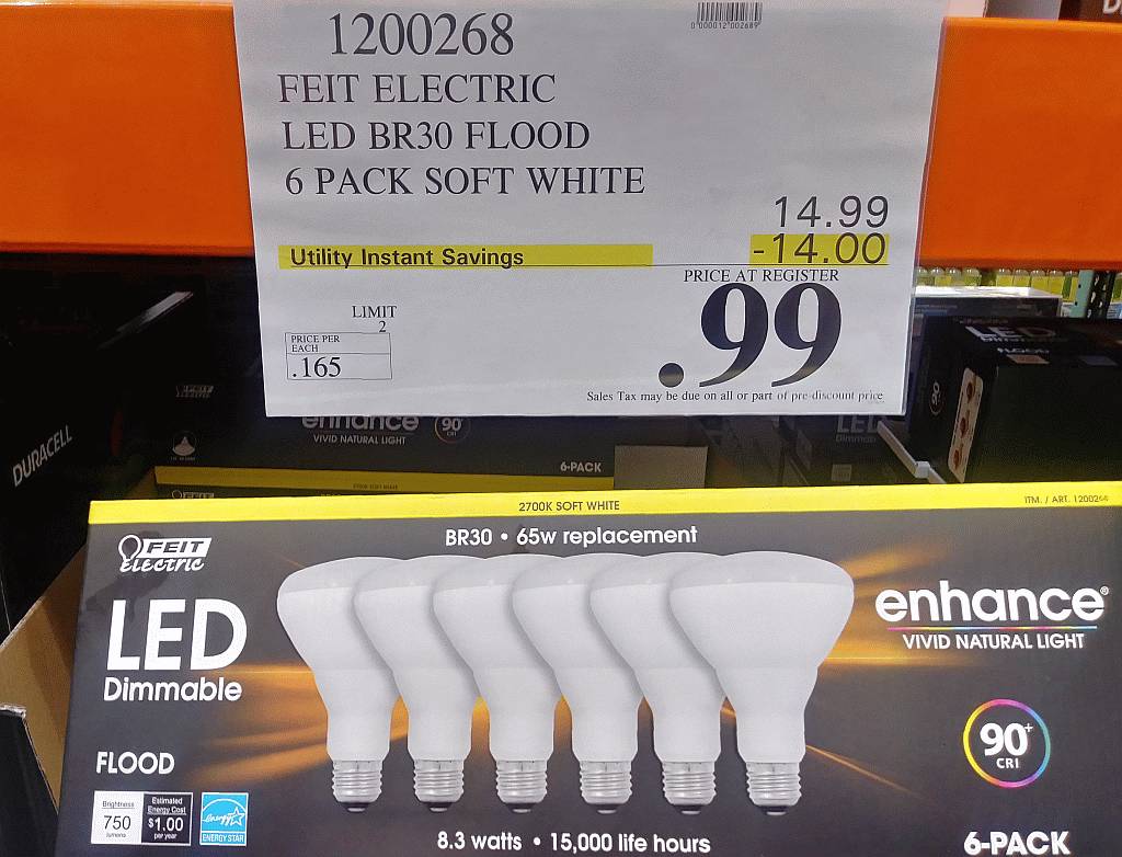
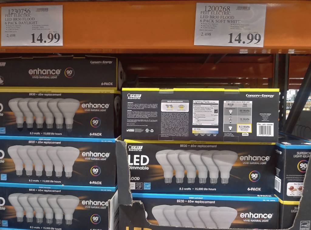
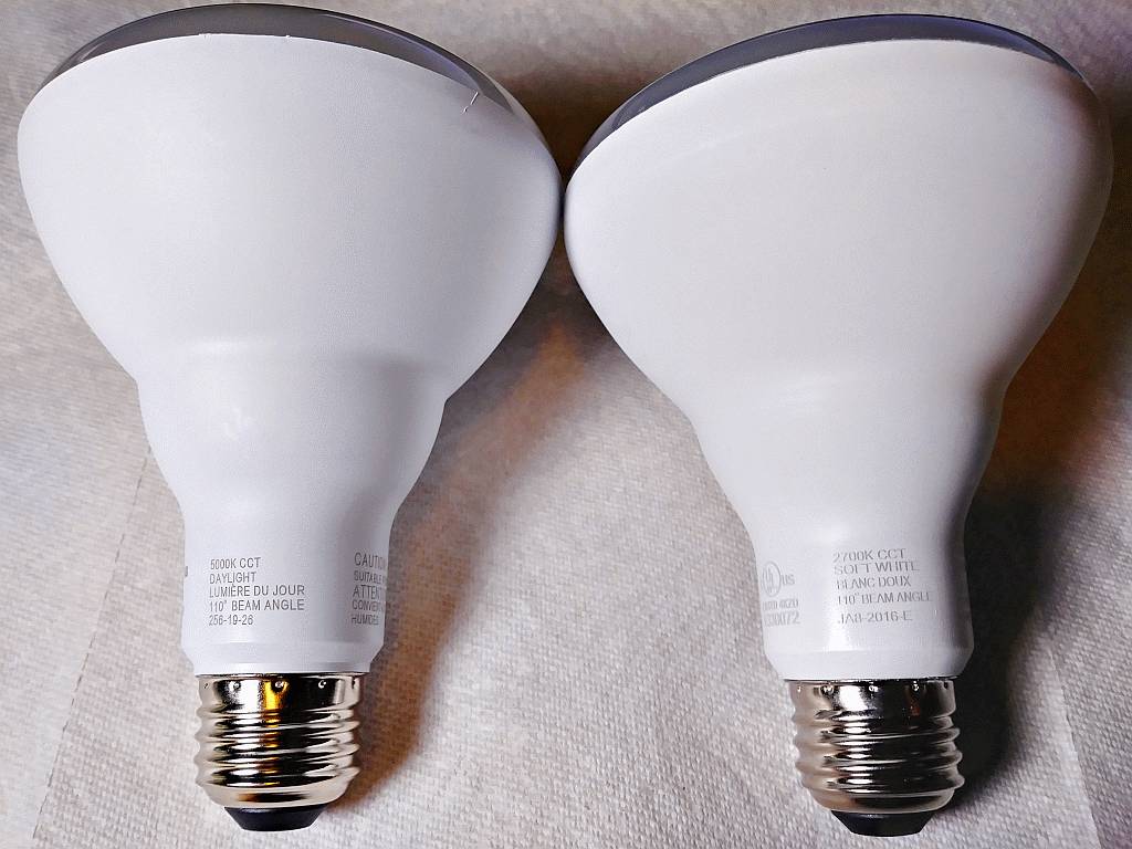
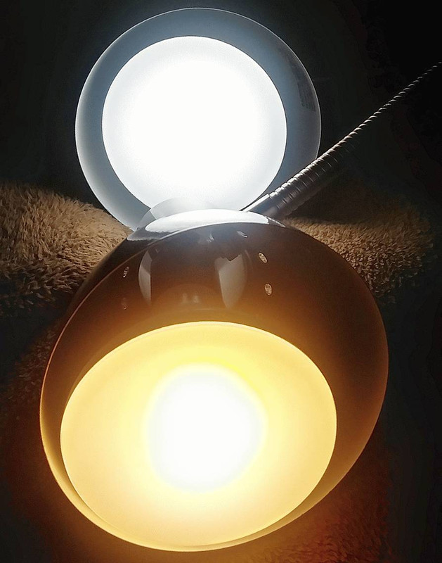
vjp2.at@at.BioStrategist.dot.dot.com: Oct 24 10:54PM

Thanks. I though it was wierd. New bulb. It has like a circle of little
dots of light which take a bit to shut down. In my mind LEDs should be the
fastest to shut down. I am deathly afraid of halogen because of fires and I
keep wondering if I got halogen instead.
 
 
- = -
Vasos Panagiotopoulos, Columbia'81+, Reagan, Mozart, Pindus
blog: panix.com/~vjp2/ruminatn.htm - = - web: panix.com/~vjp2/vasos.htm
facebook.com/vasjpan2 - linkedin.com/in/vasjpan02 - biostrategist.com
---{Nothing herein constitutes advice. Everything fully disclaimed.}---
You received this digest because you're subscribed to updates for this group. You can change your settings on the group membership page.
To unsubscribe from this group and stop receiving emails from it send an email to sci.electronics.repair+unsubscribe@googlegroups.com.

Digest for sci.electronics.repair@googlegroups.com - 5 updates in 3 topics

Arlen _G_ Holder <_arlen.george@halder.edu>: Oct 28 02:37PM

On Mon, 28 Oct 2019 05:54:02 -0700, Mike Easter wrote:
 
> My situation is very different from yours.
 
Hi Mike,
 
I understand that every situation is different, and, one of my key points
on versatility ot good tools is that even your situation is different today
than it might be five years from now (where you can repurpose stuff you
bought if it's versatile).
 
> computers and electronic devices above beside and 'around' it in
> addition to being on the floor (ground/slab) in a corner of 2 outside
> stucco walls which are made with chicken wire netting for lathing.
 
Understood. The beauty of the switch (or router) being separate from the
access point is that you can place the access point anywhere you like.
 
One thing you might consider, Mike, which works GREAT for me because I
don't want to 'climb through walls' is you can position the access point
OUTSIDE the house pointing back at the house!
 
This idea works GREAT for me!
 
I'm nestled into the side of a hill, which helps, as I can see the roof
from my back yard, where every instance is different topographically, but
even on a flat yard, you can still paint the entire house with WiFi simply
by snaking a cat5 cable to the clotheslines pole, so to speak.
 
The geometry works out such that one side of the house only has a wall and
windows to penetrate (out here, windows are solar reflective/absorptive by
code).
 
> So, for me, the important 'distance' from the router is to move the
> radio to a location which is just free airspace in every direction
> instead of being in a tight cage.
 
Understood, Mike, where it's refreshing to converse with someone like you
who has real needs and thinks of real solutions instead of having to deal
with the too many trolls who outnumber us 20:1 who simply post on Usenet
for their own amusement.
 
Given your needs are simply that the antenna needs to be in a different
location from the router/switch, I'm curious of you've looked at those
routers where the antenna itself is easily detachable and relocatable?
 
--
The beauty of good tools is that they work in a variety of situations.
Arlen _G_ Holder <_arlen.george@halder.edu>: Oct 28 02:37PM

On Mon, 28 Oct 2019 12:17:58 -0000 (UTC), Dan Purgert wrote:
 
> switched LAN ports); and the -SFP is pretty much identical, with the
> addition of the SFP port, and as I recall does (Ubiquiti 24v passive)
> PoE on all ports.
 
This is where Usenet potluck sharing shows its value:
<https://prd-www-cdn.ubnt.com/media/images/product-features/edgerouter-x-versatile-poe.jpg>
 
So I looked up those suggestions for Mike, where the first Amazon hit was:
 
$61.84 & FREE Shipping
o Ubiquiti EdgeRouter X Advanced Gigabit Ethernet Routers ER-X 256MB Storage 5 Gigabit RJ45 ports
<https://www.amazon.com/Ubiquiti-EdgeRouter-Advanced-Gigabit-Ethernet/dp/B00YFJT29C>
Where it was interesting, in the picture to see not only a POE in (which I
have on my switches also), but also a POE out (which is useful as I feel
good tools should be versatile to fit many situations over the years)
o Marketing: <https://www.ui.com/edgemax/edgerouter-x/>
o Specs: <https://dl.ubnt.com/datasheets/edgemax/EdgeRouter_X_DS.pdf>
 
Here's a review of the EdgeRouter X (aka ER-X):
<https://www.mbreviews.com/ubiquiti-edgerouter-x-review/>
 
The first hit of the ER-X-SFP was this:
$92.99 & FREE Shipping
o Ubiquiti Edgerouter X SFP - Router - Desktop - Black (ER-X-SFP)
<https://www.amazon.com/Ubiquiti-Edgerouter-SFP-Desktop-ER-X-SFP/dp/B012X45WH6/>
 
> on price / performance.
 
> Couple that with a few UAP-AC-* WiFi APs around the house, and you've
> got a great setup.
 
This is what I love about the idea of coupling a fast but inexpensive
switch to a separate access point, such as is shown in this picture:
<https://www.mbreviews.com/wp-content/uploads/2017/06/ubiquiti-edgerouter-x-6-1.jpg>
 
Note: You can put that NanoBeam NBE-M5-16 either on the POE out port, or,
you could put it on ANY port if electricity is near the location of the
transceiver, where the advantage of the POE out port is that you the
transceiver can be placed in a location that doesn't have mains power.

 
> "Cheap" can add up over time, especially if it only lasts a year or two
> (I'm currently up to 5, maybe 6 years on my APs ... probably about time
> to start thinking of getting whatever the new hotness is).
 
The one nice thing about all this Ubiquiti equipment is that they're like
hammers and screwdrivers, in that whenever you have a need, they seem to be
versatile enough to do the job well.
 
I don't have the speed needs that Mike has, but I love plugging "stuff"
into a switch where, for example, this is a radio I'm erecting outside that
is connected to a switch inside, which will paint the house from the sides:
<https://i.postimg.cc/YSfBmPkf/dumb-switch-plus-access-point.jpg>
 
--
While Usenet is replete with trolls, there are some adults who share value.
Arlen _G_ Holder <_arlen.george@halder.edu>: Oct 28 03:36AM

On Sun, 27 Oct 2019 19:17:54 -0700 (PDT), whit3rd wrote:
 
> if you have a part number, eBay or Amazon. SquareD QOB235 runs about $30
 
Thanks for that purposefully helpful advice on considering this breaker:
o Square D QOB235 2 Pole Circuit Breaker
<https://www.superbreakers.net/2-pole-circuit-breakers/square-d-qob235-35-amp>
 
It would be nice if the circuit breaker fits reasonably well in the front:
<https://i.postimg.cc/63Z0x60t/generac-circuit-breaker-panel.jpg>
 
Where, in the rear, it's less important how things bolt together:
<https://i.postimg.cc/ryNkQQvY/breaker03.jpg>
Where the Carling uses four 10-32 terminal bolts (lug type).
 
I thank you for not trolling, since it takes zero energy for the trolls to
troll while you went to the trouble to find a decent fit, where what I'll
do is trace out a paper cutout on the generator and take it with me to Home
Depot or Ace to see if the $30 "Square D QOB235 2 Pole Circuit Breaker" can
be retrofitted into that front panel hole.
 
Thanks for spending energy to bring items of value to the Usenet potluck.
 
--
For Jeff Liebermann and anyone interested, the smell of fire is all over
Silicon Valley tonight, which the winds brougth suddenly, where a pall
hangs over the valley, with a very strong odor of burning wood.
"pfjw@aol.com" <peterwieck33@gmail.com>: Oct 28 05:15AM -0700

Bob:
 
That accretion of slime that is calling itself Arlen G. Holder (this week) should not be trusted with anything sharper than a rubber spoon, much less an electrical part carrying lethal voltages and connecting in any way, shape or form to a residence, or anything else of any value.
 
Further to this, you did its work for it, as it is entirely unable muster the time to find the most obvious information on its own, but will engage in endless blather about the getting of it.
 
Put another way: Don't Feed The Troll.
 
Peter Wieck
Melrose Park, PA
tabbypurr@gmail.com: Oct 27 09:01PM -0700

On Sunday, 27 October 2019 19:22:36 UTC, Jim Horton wrote:
> that old and it's quite possible that original, antique violet ray
> devices used a different set up as I've never come across one to
> investigate for sure.
 
The main difference between antique & modern violet rays is the oldies use a self-oscillating relay, new ones use electronics to drive the coil.
 
 
NT
You received this digest because you're subscribed to updates for this group. You can change your settings on the group membership page.
To unsubscribe from this group and stop receiving emails from it send an email to sci.electronics.repair+unsubscribe@googlegroups.com.

Digest for sci.electronics.repair@googlegroups.com - 2 updates in 2 topics

Ed Pawlowski <esp@snet.xxx>: Oct 27 10:16AM -0400

On 10/27/2019 2:36 AM, Arlen _G_ Holder wrote:
> o Roger Blake (1 troll, 0 adult posts)
> o % x (1 troll, 0 adult posts)
> o Grumpy Old White Guy (1 troll, 0 adult posts)
 
I'm up to 11 now. My goal is to point out what an arrogant, snobby,
prick you are. Just the fact that you took the time to enumerate all of
this shows what a simple minded senile old man you really are.
 
Your superiority attitude makes your life more difficult because you
just grate on people. You talk about adult posts but it is YOU that is
the most childish person here. I'm not afraid to call you out on it but
you are afraid to look in a mirror and see yourself for what you are.
John-Del <ohger1s@gmail.com>: Oct 27 07:13AM -0700

On Saturday, October 26, 2019 at 1:32:58 PM UTC-4, Stu jaxon wrote:
 
> > If the tcon has two ribbons to the display, see if it runs with just one ribbon connected to the display (then try the other side).
 
> > Otherwise, you really should scope the differential signals both going into and out of the tcon to see what's going on.
 
> yep, three tabs on the left and right side of the panel are damaged. are these fixable or just trash the tv..?
 
Back when LCD TVs were *expensive*, you could replace the ribbon tab (as long as the glass substrate wasn't damaged) but you would need a re-tabbing machine and have at it. I believe there's a video on youtube on how to replace a bonded flexible ribbon tab using such a device.
 
Today, a defective screen is junk unless the problem is on the address boards. But a damaged ribbon, bad COF, or cracked glass means the recycle bin.
 
Consider that a lesson learned and paid for, and be careful on the next one..
You received this digest because you're subscribed to updates for this group. You can change your settings on the group membership page.
To unsubscribe from this group and stop receiving emails from it send an email to sci.electronics.repair+unsubscribe@googlegroups.com.

Digest for sci.electronics.repair@googlegroups.com - 25 updates in 7 topics

Cursitor Doom <curd@notformail.com>: Oct 26 08:55PM

On Sat, 26 Oct 2019 15:55:24 +0000, Cursitor Doom wrote:
 
> Which is a lot more 'modern' than the one in the Ebay advert, plus mine
> goes up to 2,500VDC.
 
Found it! Four hours of searching didn't go to waste after all.
 
http://www.richardsradios.co.uk/selectest.html
 
Not as old as I'd thought; 1972 vintage according to the advert.


--
This message may be freely reproduced without limit or charge only via
the Usenet protocol. Reproduction in whole or part through other
protocols, whether for profit or not, is conditional upon a charge of
GBP10.00 per reproduction. Publication in this manner via non-Usenet
protocols constitutes acceptance of this condition.
Phil Allison <pallison49@gmail.com>: Oct 26 03:52PM -0700

Cursitor Doom wrote:
 
---------------------------
 
> Nope. I actually used one of these:
 
> https://www.ebay.co.uk/itm/Selectest-Testmeter-Dlll-Old-Multi-
> Meter/333272931128?hash=item4d989d5b38:g:jD8AAOSwxGBdNGvF
 
** So what happened to your ohm readings ??
 
You did not post any.
 
Each junction should read about 10 to 20 ohms, on that meter.
 
B-C a bit lower than B-E, all the same for good devices that are the same.
 
FFS fess up and shame the Devil.


..... Phil
Cursitor Doom <curd@notformail.com>: Oct 27 12:31AM

** So what happened to your ohm readings ??
 
You did not post any.
 
Each junction should read about 10 to 20 ohms, on that meter.
 
B-C a bit lower than B-E, all the same for good devices that are the
same.
 
FFS fess up and shame the Devil.
 
----------------------------------------------
 
There's no point now. I have checked all 6 of those transistors and found
one faulty one as described. The question in my mind now becomes, "can
that one transistor (Q9) being partly shorted cause the voltage readings
on the other transistors to be so far out of whack?" Now most people
would probably say "just stick a new transistor in there and see if it
works" but I'm going to Spice the voltage-to-current section just out of
curiosity. Since I'm not a repair tech and time is not a factor I can do
this.
I'm lucky to have an identical board, the Y-amplifier, which is identical
in every way except that it works so I've been able to get some useful
values from measuring it under power and getting meaningful and sane
voltage readings from it to compare to the faulty one's measurements
which are all over the place.
The simulation is almost ready to run but I have other things to do right
now so it'll have to wait until tomorrow.


--
This message may be freely reproduced without limit or charge only via
the Usenet protocol. Reproduction in whole or part through other
protocols, whether for profit or not, is conditional upon a charge of
GBP10.00 per reproduction. Publication in this manner via non-Usenet
protocols constitutes acceptance of this condition.
dplatt@coop.radagast.org (Dave Platt): Oct 26 06:53PM -0700

In article <qp14d5$pv6$1@dont-email.me>,
>of the subject. I just find it baffling how such a transistor can give
>readings like those I described, with a Rc-e lower than each of its Rc-b
>and Rb-e readings!
 
That sounds to me as if the fault isn't in the B/E or B/C
junction(s). Rather, it's acting as if something ohmic is _bypassing_
the junctions.
 
I wonder whether something inside the case (e.g. some form of
contamination, debris, etc.) has fallen onto the surface of the die
and is bridging the C and E wells (or the contacts or the bond wires).
Phil Allison <pallison49@gmail.com>: Oct 26 07:13PM -0700

Dave Platt wrote:
 
------------------
 
 
> I wonder whether something inside the case (e.g. some form of
> contamination, debris, etc.) has fallen onto the surface of the die
> and is bridging the C and E wells (or the contacts or the bond wires).
 
 
** Crikey - another one who has no clue about how transistors typically fail with second breakdown or gross leakage.
 
BJTs that merely hot for a long time often develop gross leakage and reduced C-E breakdown voltage.
 
Take any TO3 pak silicon power tranny, put it in an oven at 250C for ten minutes.
 
Then test it.
 
 
..... Phil
Cursitor Doom <curd@notformail.com>: Oct 27 10:06AM

On Sat, 26 Oct 2019 18:53:22 -0700, Dave Platt wrote:
 
 
> I wonder whether something inside the case (e.g. some form of
> contamination, debris, etc.) has fallen onto the surface of the die and
> is bridging the C and E wells (or the contacts or the bond wires).
 
Phil Alison:
 
 
"** Crikey - another one who has no clue about how transistors typically
fail with second breakdown or gross leakage.
 
BJTs that merely hot for a long time often develop gross leakage and
reduced C-E breakdown voltage.
 
Take any TO3 pak silicon power tranny, put it in an oven at 250C for ten
minutes.
 
Then test it. "
 
Yes, but we're talking about a small signal transistor here and your
example of a test is a little on the extreme side to say the least.
Whilst secondary breakdown *can* happen with small signal devices, it's
much less common. I suspect your outlook is coloured by years of seeing
burned out TO-3s in audio amps, but it's nothing like as prevalent with
SSTs so let's give the guy a break, eh?


--
This message may be freely reproduced without limit or charge only via
the Usenet protocol. Reproduction in whole or part through other
protocols, whether for profit or not, is conditional upon a charge of
GBP10.00 per reproduction. Publication in this manner via non-Usenet
protocols constitutes acceptance of this condition.
Phil Allison <pallison49@gmail.com>: Oct 27 04:25AM -0700

Cursitor Doom wrote:
 
--------------------
 
 
> Then test it. "
 
 
> Yes, but we're talking about a small signal transistor here and your
> example of a test is a little on the extreme side to say the least.
 
** You have never revealed the transistor's number.
 
The OP describes it as being a "TO8 in a tin can" which makes no sense.
 
A CRO sweep amplifier is not a small signal circuit, it is large signal.
 
Maybe you meant a TO5 round metal pak like this ?
 
http://oldtube.com/2N5321-Fairchild(Philips-made)-DC335-1pc.jpg

Rated at 75V, 2A, 50MHz and 10 watts
 
The case would glow in the dark at 10 watts.
 
 
FYI:
 
I've seen hundreds like the above with shorted C-E - due to over current, over voltage or over temp.
 
Ones with low C-E resistance got lucky and were just cooked a bit.
 
Doped silicon is wacky stuff.
 
Few texts describe all or even any the failure modes.


..... Phil
Cursitor Doom <curd@notformail.com>: Oct 27 12:07PM

On Sun, 27 Oct 2019 10:06:19 +0000, Cursitor Doom wrote:
 
 
** You have never revealed the transistor's number.
 
The OP describes it as being a "TO8 in a tin can" which makes no sense.
 
A CRO sweep amplifier is not a small signal circuit, it is large signal.
 
Maybe you meant a TO5 round metal pak like this ?
 
http://oldtube.com/2N5321-Fairchild(Philips-made)-DC335-1pc.jpg

Rated at 75V, 2A, 50MHz and 10 watts
 
The case would glow in the dark at 10 watts.
 
Probably. Did I write TO-8? I meant to type TO-18. It's a 2N3251 and in
this circuit it's working well within its V&A ratings, as one would
expect with a design by Hewlett-Packard.


--
This message may be freely reproduced without limit or charge only via
the Usenet protocol. Reproduction in whole or part through other
protocols, whether for profit or not, is conditional upon a charge of
GBP10.00 per reproduction. Publication in this manner via non-Usenet
protocols constitutes acceptance of this condition.
Phil Allison <pallison49@gmail.com>: Oct 27 05:16AM -0700

Cursitor Doom wrote:
 
---------------------
 
 
> Probably. Did I write TO-8? I meant to type TO-18. It's a 2N3251 and in
> this circuit it's working well within its V&A ratings, as one would
> expect with a design by Hewlett-Packard.
 
** Pathetic.

The max ratings of any BJT on a BJC can be massively exceeded by the simplest of accidents while servicing or even cleaning.
 
Dropping a toll or screw will do it.
 
FFS get real.


.... Phil
Cursitor Doom <curd@notformail.com>: Oct 27 01:59PM

** Pathetic.

The max ratings of any BJT on a BJC can be massively exceeded by the
simplest of accidents while servicing or even cleaning.
 
Dropping a toll or screw will do it.
 
FFS get real.
 
I can't see HTH that's going to happen just out of the blue inside the
sealed casing. THE FAULT AROSE *BEFORE* THE CASE WAS EVEN REMOVED.
 
<composing myself>
Anyway, I can see your old attitude problem resurfacing and you reverting
to being your usual snarky bastard self so this thread is over AFAIC. I
will not be looking for any more replies from you via GG as you're not
adding anything of value any more.
Have a nice life and enjoy the Rugby World Cup Final Hahaha! >:-}


--
This message may be freely reproduced without limit or charge only via
the Usenet protocol. Reproduction in whole or part through other
protocols, whether for profit or not, is conditional upon a charge of
GBP10.00 per reproduction. Publication in this manner via non-Usenet
protocols constitutes acceptance of this condition.
Neon John <no@never.com>: Oct 26 03:24PM -0400

On Sat, 26 Oct 2019 10:38:57 -0400, Jim Horton <jhorton@nospam.net>
wrote:
 
>one, I bought new. It would have greatly interfered plugged into the
>same outlet as everything else and only produces 2" sparks but at a much
>higher frequency.
 
That is not a Tesla coil. It is an Oudin coil. Much different
principle of operation. Take the bottom off one and the way it works
will be evident.
 
Unlike a well designed Tesla coil which won't shock you, that Oudin
coil will. Hard!
 
John
John DeArmond
http://www.neon-john.com
http://www.tnduction.com
Tellico Plains, Occupied TN
See website for email address
tabbypurr@gmail.com: Oct 26 08:31PM -0700

On Saturday, 26 October 2019 20:24:49 UTC+1, Neon John wrote:
> will be evident.
 
> Unlike a well designed Tesla coil which won't shock you, that Oudin
> coil will. Hard!
 
I always understood the Oudin & Tesla were much the same. What's the difference?
 
 
NT
Cursitor Doom <curd@notformail.com>: Oct 27 10:16AM

On Sat, 26 Oct 2019 20:31:15 -0700, tabbypurr wrote:

> I always understood the Oudin & Tesla were much the same. What's the
> difference?
 
The main difference is no one's ever heard of an "Oudin coil" :-)


--
This message may be freely reproduced without limit or charge only via
the Usenet protocol. Reproduction in whole or part through other
protocols, whether for profit or not, is conditional upon a charge of
GBP10.00 per reproduction. Publication in this manner via non-Usenet
protocols constitutes acceptance of this condition.
Fox's Mercantile <jdangus@att.net>: Oct 27 08:35AM -0500

On 10/27/19 5:16 AM, Cursitor Doom wrote:
 
>> I always understood the Oudin & Tesla were much the same. What's the
>> difference?
 
> The main difference is no one's ever heard of an "Oudin coil" :-)
 
You mean you've never heard of it.
In the words of Jon Stewart, "You can look this shit up you know."
 
<https://en.wikipedia.org/wiki/Oudin_coil>


--
"I am a river to my people."
Jeff-1.0
WA6FWi
http:foxsmercantile.com
Arlen _G_ Holder <_arlen.george@halder.edu>: Oct 27 08:14AM

UPDATE:
 
Hi Jeff,
 
As you're aware, PG&E has cut our power here near Santa Cruz and the hills
surrounding Silicon Valley, where the fact I'm able to post this means I
figured out what the problem was with the power from the generator not
getting to the house.
<https://i.postimg.cc/G37D8Jq6/breaker01.jpg>
 
I had _thought_ it was the transfer switch, simply because a couple of
those SBS-2 600V 2Amp fast acting ferrule fuses were missing, but it turns
out that when I replaced the two missing fuses, nothing changed.
<https://i.postimg.cc/ryNkQQvY/breaker03.jpg>
 
It turns out that half of the part #5 was broken inside (invisibly so)
<https://i.postimg.cc/qq326cBh/Generac-Control-Panel-9067-9-16345-Page-19.jpg>
o Generac Part Number #74969 35Amp Circuit Breaker
 
I'm not sure if that's the same part as "CB1" in bottom right of this page:
<https://i.postimg.cc/Zqf00Y5K/Generac-Generator-Wiriing-Diagram-9067-9-16345-Page-14.jpg>
 
But it's Generac Part Number 74969 35 Amp Circuit Breaker (2 ganged poles),
which disconnects 120VAC power based on my measurements on the breaker.
<https://i.postimg.cc/vmTTdpdB/breaker02.jpg>
 
This is what it says on the circuit breaker itself:
Carling Switch Inc.
AA2.B0.24.635.5D1.C
FL AMP 35
MAX VOLTS 227 (? hard to tell)
HERTZ 50/60
DELAY 04 (? hard to tell)
TRIP AMPS 43 (? hard to tell)
Mexico 9513 (probably the 13th week in 1995)
 
Where the complete circuit diagram is outlined already in this older post:
<https://groups.google.com/d/msg/sci.electronics.repair/QhSY4KWN-Kw/P-R0-y6CBAAJ>
 
In summary, there were two problems concurrently:
1. The fuses were missing in the transfer switch
2. Half the circuit breaker was internally broken
 
The result was that there was no electricity in the house when the PG&E
power went out until I replaced the fuses; and there was only electricity
to half the house. The 35Amp ganged circuit breaker has two "LINE" and two
"LOAD" terminals, where, each circuit breaker innervates half the house.
 
--
Solving electrical problems with advice from helpful posters on Usenet.
Arlen _G_ Holder <_arlen.george@halder.edu>: Oct 26 09:18PM

UPDATE:
 
While these devices all come with debugging tools, it's useful to let users
know that on Android (but unfortunately not on iOS), there are modern
powerful debugging tools that help you debug your WiFi signals:
<https://i.postimg.cc/BZrZpDyp/debug-apps.jpg>
 
For example, I just snapped these screenshots of one app in use today:
<https://i.postimg.cc/FRqR6DSq/android-wifi-analyzer.jpg>
 
If you know of any iOS apps that do the same, please let me know:
<<https://i.postimg.cc/0NYJn7mF/nanobridge-nanobeam.jpg>>
 
As it would be nice on the larger iPad screen if such iOS tools existed.
<https://i.postimg.cc/SK04C6zL/ubiquiti-bullet-M2-hp.jpg>
 
These Android free ad-free tools are useful to test temporary bridges:
<https://i.postimg.cc/vT0Krpfc/laptop-nanobeam-horn.jpg>
 
With and without the horns attached to the high-gain antennas:
<https://i.postimg.cc/Hs0NWSKr/laptopnanobeam.jpg>
 
Where it's your choice whether to use the horn alone or in combination with
the antenna, which turns the omni horn into a narrow beam WiFi extender:
<https://i.postimg.cc/D0vfqM3p/horns.jpg>
 
Which, depending on various factors could be miles of point-to-point range:
<https://i.postimg.cc/QMNv5FBC/typical-range-ptp.jpg>
(where, as Johann Beretta noted, that screenshot is with AirMax enabled)
 
Modern WiFi debugging apps are useful when you set up APs at home, where,
for example, you can instantly convert a dumb switch to a WiFi AP & then
test with your Android phone how strong the signal is around the house:
<https://i.postimg.cc/JhyCRT69/horn-to-switch.jpg>
 
Or, if you have a spare old router, debug the extension of its range:
<https://i.postimg.cc/25NdBZ7f/horn-to-router.jpg>
Given that laptops are notoriously anemic when it comes to WiFi range.
 
You can also debug when you add bridge a desktop without WiFi to WiFi
<https://i.postimg.cc/6QJqK6Cj/desktop02.jpg>
 
And you can see the difference in range on your phone, when you have both:
<https://i.postimg.cc/Gh22Sb2N/desktop.jpg>
 
Yes, there are already UNIX-like tools inherent in the router software:
<https://i.postimg.cc/yx4CgWYt/mikrotik-router-config.jpg>
 
But they only work for an individual transceiver (radio & router):
<https://i.postimg.cc/DfQJq437/mikrotikrouter.jpg>
 
And, they're different software for each transceiver brand:
<https://i.postimg.cc/Bv0wZbDh/pbe-m2-400-802-11-wifi-setting.jpg>
 
Where, unfortunately, iOS just doesn't have this modern app functionality:
<https://i.postimg.cc/25v3FT6S/debug-on-android.jpg>
 
In summary, when you set up these devices, your Android phone instantly
becomes a very useful modern WiFi testing tool, where if you know of any
iOS app functionality on the Apple App Store that does the same thing,
please let me know as I've looked in vain for years on end for such modern
app functionality to exist on my much larger screen iPads.
<https://i.postimg.cc/YqTk0q1T/ap.jpg>
 
--
Using mobile devices to their fullest functional capabilities every day!
Arlen _G_ Holder <_arlen.george@halder.edu>: Oct 26 09:56PM

On Thu, 24 Oct 2019 01:24:18 -0700, Johann Beretta wrote:
 
> that there will be some cases of interference, but with WISP gear (I
> don't know what the cell sites are using) having a 2-5 mile range is a
> hell of a lot better than the nearly unlimited range of 5 GHz.
 
UPDATE:
 
Decided to send this before PG&E shuts off the power, which is scheduled to
go off for a few days in an hour or so (as far as PG&E has explained it).
(California has 3rd-world power reliability at the top of 1st-world costs!)
 
Given this thread is a public potluck of useful sharing, what I would love
is if Jeff and/or Johann could help shed a summary of light on the various
"options" that are available to mere homeowners, who have Ubiquiti radios.
 
For example, we haven't covered the free mobile device available debuggers:
<https://i.postimg.cc/FRqR6DSq/android-wifi-analyzer.jpg>
 
Where, as far as I know, there's nothing like these tools on iOS (sadly):
<https://i.postimg.cc/25v3FT6S/debug-on-android.jpg>
(I wish such modern app functionality existed on iOS, so if anyone out
there knows iOS better than I do, please let me know where to get it).
 
 
Even on the router software itself, we covered some things that are of
general interest to users, but, for example, we didn't mention AirSelect:
<https://i.postimg.cc/kg5LKkz9/pbe-m2-400-airmax-setting.jpg>
 
And, we didn't dig into details of the versatile use of wireless options:
o Station
o Access Point
o AP-Repeater
<https://i.postimg.cc/htQ469sQ/pbe-m2-400-ap-station.jpg>
 
Nor did we distinguish between the various network options, for example:
o Bridge
o Router
o SOHO Router
<https://i.postimg.cc/gcBWpxnV/pbe-m2-400-bridge-router.jpg>
 
Personally, I don't know them well enough to summarize each option above,
but maybe the experts here can write a quick one-line summary for each so
that everyone benefits in this purposefully helpful Usenet sharing potluck.
 
--
Usenet is a wonderful place to share common items of technical interest.
Jeff Liebermann <jeffl@cruzio.com>: Oct 26 03:41PM -0700

On Sat, 26 Oct 2019 21:56:12 -0000 (UTC), Arlen _G_ Holder
 
>Decided to send this before PG&E shuts off the power, which is scheduled to
>go off for a few days in an hour or so (as far as PG&E has explained it).
>(California has 3rd-world power reliability at the top of 1st-world costs!)
 
I just spend the morning charging every rechargeable battery that I
could find in my house and car. I had no idea I had that many
batteries and chargers. Where did they call come from?
 
>Given this thread is a public potluck of useful sharing, what I would love
>is if Jeff and/or Johann could help shed a summary of light on the various
>"options" that are available to mere homeowners, who have Ubiquiti radios.
 
Pass. I'm not a salesman and really don't care what users do with
their computers and equipment. I'm just the guy that makes them work,
or explains to them how they work so they can make them work without
my involvement. I also avoid recommending anything that I haven't
personally broken, errr... tested, because of the large number of
surprises I find, and lies in the data sheets. That means I don't
know anything about the various "options" available to those who don't
know what they want. See a salesman or system integrator for details
on those.
 
Unfortunately, I've played with everything you've mentioned, so you'll
get the benefits of my wisdom and sarcasm.
 
>For example, we haven't covered the free mobile device available debuggers:
><https://i.postimg.cc/FRqR6DSq/android-wifi-analyzer.jpg>
 
Kinda looks like a variation on the original (and still best) Wi-Fi
Analyzer Android app:
<https://play.google.com/store/apps/details?id=com.farproc.wifi.analyzer&hl=en_US>
 
><https://i.postimg.cc/25v3FT6S/debug-on-android.jpg>
>(I wish such modern app functionality existed on iOS, so if anyone out
>there knows iOS better than I do, please let me know where to get it).
 
In the words of the late great Steve Jobs, "You don't need to know".
 
>Even on the router software itself, we covered some things that are of
>general interest to users, but, for example, we didn't mention AirSelect:
><https://i.postimg.cc/kg5LKkz9/pbe-m2-400-airmax-setting.jpg>
 
What is Air Select?
<https://community.ui.com/questions/What-is-Air-Select/ab1949f3-8f39-42ac-8821-df5dcb2283a1>
It's a variation on having the wireless access point change channel in
a futile effort to find one that is empty. The client radios will all
follow the channel change without dropping the connection. Other
manufacturers WAP's and routers have the same feature. I always leave
it disabled because there are a small number of weird client radios
that fail to follow the channel change, and end up associated with a
totally different WAP or router on a different SSID. Leaving it off
has almost totally eliminated the "can't connect" phone calls.
 
>o Access Point
>o AP-Repeater
><https://i.postimg.cc/htQ469sQ/pbe-m2-400-ap-station.jpg>
 
Station means "client bridge".
Access point means "wireless access point", "multipoint wireless
bridge", "wireless router with the WAN port disconnected", or some
other conglomeration of impressive sounding buzzwords.
AP repeater means "interference and congestion generator with the
added bonus of cutting maximum throughput in half".
 
>o Router
>o SOHO Router
><https://i.postimg.cc/gcBWpxnV/pbe-m2-400-bridge-router.jpg>
 
Bridging is what ALL wi-fi devices do. It means they work on Layer 2
of the TCP/IP stack and use MAC addresses to switch packets to the
correct destination.
Router is Layer 3 of the TCP/IP stack. It adds IP addresses.
SOHO Router means "Small Office, Home Office router". That's a
commodity router with all the features and functions needed to provide
business class performance and reliability removed to keep the price
low.
 
>Personally, I don't know them well enough to summarize each option above,
>but maybe the experts here can write a quick one-line summary for each so
>that everyone benefits in this purposefully helpful Usenet sharing potluck.
 
I only share with those who can pass a credit check.
 
--
Jeff Liebermann jeffl@cruzio.com
150 Felker St #D http://www.LearnByDestroying.com
Santa Cruz CA 95060 http://802.11junk.com
Skype: JeffLiebermann AE6KS 831-336-2558
Arlen _G_ Holder <_arlen.george@halder.edu>: Oct 27 01:30AM

On Sat, 26 Oct 2019 15:41:08 -0700, Jeff Liebermann wrote:
 
 
> I just spend the morning charging every rechargeable battery that I
> could find in my house and car. I had no idea I had that many
> batteries and chargers. Where did they call come from?
 
Hi Jeff,
 
I know what you mean about getting ready for the PG&E outage today!
 
Up here, we all have generators, because our power goes off on average once
a month for a day or two each time (I could email you the PG&E-supplied
accurate spreadsheet of just the last 30 sustained power outages, for
example, which I provided to the CPUC to show how PG&E provides unreliable
power at top-tier prices).
 
Unfortunately, the Santa Cruz Costco is out of those great gas cans!
<https://i.postimg.cc/26qmJCpz/costco-gas-cans.jpg>
 
Luckily, at Costco in Santa Cruz by 17 & 1, the batteries are currently on
sale as are the flashlights (and BR30 LED bulbs for a dollar a bulb:
<https://i.postimg.cc/T1d8xxFL/costco-br30-led-sales-price.jpg?
 
When those 750 lumens 15K life hours BR30 ceiling bulbs are $2.50 each
<https://i.postimg.cc/KjRNBsgp/costco-br30-led-normal-price.jpg>
 
Where I always have to get the 2,700 degrees for the wife, and the 5,000
degree BR30 bulbs for me.
<https://i.postimg.cc/WzCdK5Yy/costco-br30-side-by-side.jpg>
 
But where I then can't mix & match in the house, since they're different:
<https://i.postimg.cc/1XGzCy68/costco-br30-color-at-night.jpg>
 
Cost of LED Bulbs = $11.94 (plus CA sales tax of $8.32)
which, of course, is imputed on the original price, but which accounts for
a whoppingly huge 70% of the actual sales price at the register)
<https://i.postimg.cc/kMcwZKcg/costco-led-bulb-receipt.jpg>
 
BTW, I measured the $6 3-pound cooked chicken since I was stocking up
<https://i.postimg.cc/k5JpkFHJ/costco-chicken-at-the-start.jpg>
where I separated the hot gristle and weighted it separately:
<https://i.postimg.cc/LsG8yXyV/costco-chicken-gristle-separated.jpg>
From the hot meat with no bones and none of the sugar/salt solution:
<https://i.postimg.cc/wBR6sz6R/costco-chicken-meat-separated.jpg>
Where the gristle was about 1-3/4 pounds of the advertised 3 pounds
<https://i.postimg.cc/W1FR57xQ/costco-chicken-gristle-weight.jpg>
And the meat turned out to be just under 3 pounds of the 3 pound weight
<https://i.postimg.cc/JnKdry9N/costco-chicken-meat-weight.jpg>
 
> their computers and equipment. I'm just the guy that makes them work,
> or explains to them how they work so they can make them work without
> my involvement.
 
Fair enough.
 
I like to explain things, to people who care to learn, and I love even more
being able to do stuff that people don't normally do (such as what these
radios allow for).
 
I admit I'm terrible at dealing with the trolls though, as it's
inconceivable to me that these people have zero purposefully helpful intent
in everything they do.
 
> I also avoid recommending anything that I haven't
> personally broken, errr... tested, because of the large number of
> surprises I find, and lies in the data sheets.
 
Yup. I understand. I still remember you wrote the best description on all
of Usenet for the lies that router sales pitches spew, particularly about
the "power" figures, where that's where I learned only the FCC knows for
sure. :)
 
> on those.
 
> Unfortunately, I've played with everything you've mentioned, so you'll
> get the benefits of my wisdom and sarcasm.
 
Understood. And accepted.
 
There are so many options to these radios that I don't even know all the
things they can do for us, where I mostly use them for three things:
1. Point to multipoint (instantly adding an access point to "an RJ45")
2. Point to multipoint (instantly bridging Ethernet to WiFi networks)
3. Point to point (for longer LOS hauls, where mine is 6 miles only)
 
But there's a LOT more we can do with these radios (e.g., they're routers
too, and they are repeaters also, etc.).
 
 
> Kinda looks like a variation on the original (and still best) Wi-Fi
> Analyzer Android app:
> <https://play.google.com/store/apps/details?id=com.farproc.wifi.analyzer&hl=en_US>
 
Yup. You and I went over these apps in gory detail a few years ago.
 
Where I'm glad you care about your credibility, as I do, and where you
listed the unique name for the WiFi Analyzer app you like, as I have, oh,
let me check, give me a second ... ok... I have 6 apps alone named exactly
that (i.e., "WiFi Analyzer") on my Android phone at this very minute:
<https://i.postimg.cc/ZqH1RDNv/debug-wifi-on-android.jpg>
o Wifi Analyser <com.keuwl.wifi>
o Wifi Analyzer <com.farproc.wifi.analyzer>
o Wifi Analyzer <com.farproc.wifi.analyzer.classic>
o WiFi Analyzer <abdelrahman.wifianalyzerpro>
o WiFi Analyzer <uk.co.soapysoft.wifianalyzer>
o WiFi Analyzer <com.wifianalyzer.networktools.networkanalyzer>
 
And yet, on iOS, there are zero. Sigh. The iPhone users don't even realize
how utterly primitive the app choices are on their beloved platform.
I test software like you test hardware, so I know them all.
 
I just wish my iOS iPads could have this kind of modern functionality.
Sigh.
 
(What's odd is that the Apple Apologists incessantly claim the
functionality exists, and they even did a Youtube video condemning me
because I proved they simply fabricated imaginary iOS functionality, as
they always seem to do - which is really odd for adults to try to pull).
o It's a fact iOS devices can't even graph Wi-Fi signal strength over time
<https://groups.google.com/d/msg/misc.phone.mobile.iphone/PZuec56EWB0/rX-L9xbYAQAJ>
 
Here's the video Snit did about me, where it's hilarious that none of the
Apple Apologists ever even _once_ looked at the Y axis!
<https://youtu.be/7QaABa6DFIo>
 
>>(I wish such modern app functionality existed on iOS, so if anyone out
>>there knows iOS better than I do, please let me know where to get it).
 
> In the words of the late great Steve Jobs, "You don't need to know".
 
You are correct that the Apple philosophy is to limit what you can do,
but what's strange about the many Apple Apologists is that they fabricate
imaginary iOS functionality all the time....
 
Why?
I don't know why.
 
But they do it all the time.
o What are common well-verified psychological traits of Apple Apologists
<https://groups.google.com/d/msg/misc.phone.mobile.iphone/18ARDsEOPzM/veU8FwAjBQAJ>
 
They don't care that their credibility is shit the moment they do that.
o Meanwhile, I've never once posted something that wasn't a fact (AFAIK).
 
I care about my credibility - which is why the very fact that there are so
many trolls who infest this thread who don't give a whit about their lack
of credibility astounds me - since adults are supposed to provide value.
 
Sigh.
 
> <https://community.ui.com/questions/What-is-Air-Select/ab1949f3-8f39-42ac-8821-df5dcb2283a1>
> It's a variation on having the wireless access point change channel in
> a futile effort to find one that is empty.
 
hehhehheh...
 
> that fail to follow the channel change, and end up associated with a
> totally different WAP or router on a different SSID. Leaving it off
> has almost totally eliminated the "can't connect" phone calls.
 
Now that's interesting.
 
If you were an Apple Apologist, I would have to flip a coin to see if I
believed you, but since I know you, for many years, to be credible (as am
I), I believe you a priori.
 
Thanks for that advice where I will take it to heart since you have always
been credible, if a bit self effacing (I love the photo of you in your park
ranger outfit by the way ... it was so 70s ... but it makes you human on
Usenet!). :)

> other conglomeration of impressive sounding buzzwords.
> AP repeater means "interference and congestion generator with the
> added bonus of cutting maximum throughput in half".
 
Hehhehheh... I didn't quite get all the technical jargon, but I did get the
jokes as the repeater does double duty, hence half the throughput.
 
I've never put the Ubiquiti radios on anything but bridge or access point,
so it's good information to know, where I love that these tools, like an
Android phone, turn out to be so versatile that they do far more than we
know at first.
 
>>o SOHO Router
>><https://i.postimg.cc/gcBWpxnV/pbe-m2-400-bridge-router.jpg>
 
> Bridging is what ALL wi-fi devices do. It means they work on Layer 2
 
Thanks for that summary which makes total sense.
 
> of the TCP/IP stack and use MAC addresses to switch packets to the
> correct destination.
> Router is Layer 3 of the TCP/IP stack. It adds IP addresses.
 
I've never used this, but it seems useful if we plug it into a switch where
we can have multiple devices on that switch, where, I guess, each gets its
own IP address from the Ubiquiti router.
 
Is that about right for the router (given it's only one RJ45 port coming
out of the radio)?
 
> commodity router with all the features and functions needed to provide
> business class performance and reliability removed to keep the price
> low.
 
What I'm guessing is that the "router" versus "soho router" option must be
giving the Ubiquiti radio "more options" that are related to routing.
 
As I said, I have never used that "soho router" option in the Ubiquiti
AirOS software, so I don't even know if I've ever needed to use it as a
"Soho router" and didn't know it.
 
>>but maybe the experts here can write a quick one-line summary for each so
>>that everyone benefits in this purposefully helpful Usenet sharing potluck.
 
> I only share with those who can pass a credit check.
 
Thanks for that advice, where you've helped me and many others cheerfully
over the years, where I still remember when I was trying to change MAC
addresses and IMEI numbers (many years ago when it mattered), and you
advised against it (and you explained that the one MAC address you can
change isn't the one you want to change, etc.).
 
My point is that your advice, over the years, has always been credible.
As am I.
 
Thanks - and - well - we were 'scheduled' for that PG&E outage, but we
didn't get it yet, so I had better send this off to you now before it
happens.
 
--
Usenet is a pairing of the most helpful minds to benefit everyone who can.
Arlen _G_ Holder <_arlen.george@halder.edu>: Oct 27 06:36AM

SUMMARY:
 
What I love is that the permanent Usenet record, will clearly show ...
in this thread, we covered a lot of technical ground, including:
1. Software on iOS & Android to debug WiFi signal strength over time
2. Hardware to vastly increase Access Point range over anemic consumer crap
3. Hardware to bridge Ethernet to WiFi that also vastly increases range
4. Using pro equipment that costs about the same as anemic consumer crap
 
All of this was done with only a handful of adult posters named below:
o Jeff Liebermann
o Johann Beretta
o Gary
o Gavin
o Frank
o Terry Coombs
o Xeno
o rbowman (only some of the time he posted as an adult)
o Bod
o John Kuthe
 
This isn't my first rodeo on Usenet, where I employed completely different
techniques in this thread, in order to prove that the trolls would troll no
matter how much you ignored them (see the statistics below for example).
 
The value here is that the permanent record showed that it doesn't matter
whether you feed the trolls (as in the case of trader_4) or not (as in the
case of Ed Pawlowsi & Fox's Mercantile, aka Snit), the trolls will
outnumber the adult posters something like 20 to 1, as shown by the number
of trolls posted by the well known list of common trolls listed below.
 
None of these trolls added value, nor did any post with purposefully
helpful intent, simply because, IMHO, they have no purposefully helpful
intent (i.e., they post for their own amusement), and, worse, they can't
possibly add value since the lack the basic knowledge required to do so.
o trader_4 (25 trolls, 2 adult posts)
o Ed Pawlowski (10 trolls, 0 adult posts)
o Fox' Mercantile (9 trolls, 1 adult post)
o Cindy Hamilton (9 trolls, 1 adult post)
o dpb (3 trolls, 0 adult posts)
o Clare Snyder (2 trolls, 0 adult posts)
o Al Gore (2 trolls, 0 adult posts)
o Trumpster (1 troll, 0 adult posts)
o devnull (1 troll, 0 adult posts)
o Troll (1 troll, 0 adult posts)
o gfretwell (1 troll, 0 adult posts)
o Roger Blake (1 troll, 0 adult posts)
o % x (1 troll, 0 adult posts)
o Grumpy Old White Guy (1 troll, 0 adult posts)
 
Also, the ground we covered was EXTREMELY DETAILED, where the permanent
record will show we gave settings, distances, model numbers, transmit
power, antenna gain, setup instructions, power instructions, line of sight
instructions, etc., such that any ADULT willing to learn from this thread,
has a wealth of knowledge that is available to him.
 
As just a sample of the wealth of knowledge in this thread, these were
posted, each of which takes time and energy & expertise to compose:
o <https://i.postimg.cc/05S6CtNn/align03.jpg>
o <https://i.postimg.cc/0NYJn7mF/nanobridge-nanobeam.jpg>
o <https://i.postimg.cc/25NdBZ7f/horn-to-router.jpg>
o <https://i.postimg.cc/25v3FT6S/debug-on-android.jpg>
o <https://i.postimg.cc/6QJqK6Cj/desktop02.jpg>
o <https://i.postimg.cc/6QQ2Lt74/align02.jpg>
o <https://i.postimg.cc/905nFgxX/nanobeamnanobridge.jpg>
o <https://i.postimg.cc/bNMMZ0Nv/wifi-speed.jpg>
o <https://i.postimg.cc/Bv0wZbDh/pbe-m2-400-802-11-wifi-setting.jpg>
o <https://i.postimg.cc/BZrZpDyp/debug-apps.jpg>
o <https://i.postimg.cc/cHLndnbY/antenna.jpg>
o <https://i.postimg.cc/CLBXc080/antenna03.jpg>
o <https://i.postimg.cc/D0vfqM3p/horns.jpg>
o <https://i.postimg.cc/DfQJq437/mikrotikrouter.jpg>
o <https://i.postimg.cc/DZccY2YD/decibels.jpg>
o <https://i.postimg.cc/Dzq9Bsjs/pb-m2-400-nanobeam.jpg>
o <https://i.postimg.cc/FRqR6DSq/android-wifi-analyzer.jpg>
o <https://i.postimg.cc/gcBWpxnV/pbe-m2-400-bridge-router.jpg>
o <https://i.postimg.cc/Gh22Sb2N/desktop.jpg>
o <https://i.postimg.cc/GpCG1H3G/airviewneedsjava.jpg>
o <https://i.postimg.cc/Hs0NWSKr/laptopnanobeam.jpg>
o <https://i.postimg.cc/htQ469sQ/pbe-m2-400-ap-station.jpg>
o <https://i.postimg.cc/JhyCRT69/horn-to-switch.jpg>
o <https://i.postimg.cc/JzpthvTr/align04.jpg>
o <https://i.postimg.cc/kg5LKkz9/pbe-m2-400-airmax-setting.jpg>
o <https://i.postimg.cc/nrkz5mgs/antenna01.jpg>
o <https://i.postimg.cc/pLXCzFxC/powerbeam-nanobeam.jpg>
o <https://i.postimg.cc/QMNv5FBC/typical-range-ptp.jpg>
o <https://i.postimg.cc/s2c2L8Wd/mikrotik-router.jpg>
o <https://i.postimg.cc/sfkHW6WG/align.jpg>
o <https://i.postimg.cc/SK04C6zL/ubiquiti-bullet-M2-hp.jpg>
o <https://i.postimg.cc/tCxLW2ZN/align01.jpg>
o <https://i.postimg.cc/vT0Krpfc/laptop-nanobeam-horn.jpg>
o <https://i.postimg.cc/VvqLKQtQ/wifi.jpg>
o <https://i.postimg.cc/XJChDCPr/spare-access-points.jpg>
o <https://i.postimg.cc/yNXw0TZS/antenna02.jpg>
o <https://i.postimg.cc/YqTk0q1T/ap.jpg>
o <https://i.postimg.cc/yx4CgWYt/mikrotik-router-config.jpg>
o <https://dl.ubnt.com/datasheets/rocketdish/rd_ds_web.pdf
o <https://dl.ubnt.com/datasheets/rocketm/RocketM_DS.pdf
 
In summary, we accomplished a lot in this thread, where the permanent
record will show that the common trolls will troll if you feed them (e.g.,
the experiment with trader_4), and they'll troll even if you ignore them
(e.g., the experiment with Ed Pawlowski & Fox' Mercantile (aka Snit).
 
The value added of this thread, IMHO, is that we covered, in detail, a
method to vastly increase the range of your access points or bridges to
WiFi, should you need that range, using professional equipment which costs
about the same as the anemic consumer equipment costs in the box stores.
 
--
Usenet is a potluck where adults gather to share knowledge which is then
archived in the permanent record for all to view now & decades from now.
Phil Allison <pallison49@gmail.com>: Oct 26 08:52PM -0700

Fox's Mercantile wrote:
 
------------------------
> > good luck with that.  Usenet is the wild west of the
> > internet & everybody does what they damn well please.
 
> I know that. You know that.
 
** Quoting properly is something YOU do not do.
 
One should always post under the particular words of another you are responding to and also BE about them.
 
No context shifting, posting some idiot jibe or introducing red herring.
 
And the big one:
 
If you have nothing worthwhile to post - POST NOTHING !!
 
Keeping on posting to have the last word, so you never admit error or defeat, is the act of an asshole.
 
 
.... Phil
Tim Schwartz <tim@bristolnj.com>: Oct 26 05:25PM -0400

Hi,
 
The D40D5 is an obsolete case style, but a TO-220 transistor can be
used though the pin out may be different. The specs for the D40D5 are here:
 
https://pdf1.alldatasheet.com/datasheet-pdf/view/130481/ETC1/D40D5.html
 
Many common TO-220 devices will work, like a TIP-41C or a BD-911. You
may have to put sleeving on the leads and twist them around to the
correct hole, depending on the board.
 
It would be helpful if you mentioned what product you are working on,
as you might get better advice.
 
Regards,
Tim
 
 
On 10/25/2019 7:34 PM, TheExperimenter wrote:
TheExperimenter <theexp8712@noaol.net>: Oct 26 05:38PM -0400

On 10/26/19 5:25 PM, Tim Schwartz wrote:
> on, as you might get better advice.
 
> Regards,
> Tim
 
Ok, I'll try it here too. I posted this in another group and finally
reluctantly shared what it was for to be met with almost instant
criticism, but here we go (I'm just quoting what I wrote in the other
group):
 
Unfortunately, the exact schematic does not appear online and is
copyrighted. However, it appeared in Radio Electronics Magazine
September 1986, p. 42 stun gun. A similar one adapted from the article
is here, but does not use the same components:
 
http://www.learningelectronics.net/VA3AVR/circ/hv/stungun/stungun.html
 
I built the gun from the kit in 1994, but my wife used it a month ago
and burned it out while scaring off a would be attacker.
 
I originally contacted the firm that made it, but have not heard back
after several weeks, so I went parts looking myself. I don't trust the
ones with the puny "400 KV" modules that seem to be front and center
now. This one really worked and was tested scientifically at the time
which is why I'd like to get the replacement components.
Phil Allison <pallison49@gmail.com>: Oct 26 05:51PM -0700

TheExperimenter Moron wrote:
 
-------------------------
 
 
** WARNING WARNING !!!
 
 
The above poster is a dangerous lunatic.
 
He or his wife want to KILL someone by HV electrocution.
 
DO NOT assist in the repair of a lethal weapon.
 

http://www.learningelectronics.net/VA3AVR/circ/hv/stungun/stungun.html
 
** Jesus H Christ !!!
 
READ the warnings in the yellow box and the RED print further down.


..... Phil
Stu jaxon <stankowalski02@gmail.com>: Oct 26 10:32AM -0700

On Thursday, October 24, 2019 at 5:59:24 PM UTC-4, John-Del wrote:
 
> Something may have gone wrong when you removed the display from the frame. It could have been a static discharge or a damaged ribbon on (one of) the address board(s).
 
> If the tcon has two ribbons to the display, see if it runs with just one ribbon connected to the display (then try the other side).
 
> Otherwise, you really should scope the differential signals both going into and out of the tcon to see what's going on.
 
yep, three tabs on the left and right side of the panel are damaged. are these fixable or just trash the tv..?
You received this digest because you're subscribed to updates for this group. You can change your settings on the group membership page.
To unsubscribe from this group and stop receiving emails from it send an email to sci.electronics.repair+unsubscribe@googlegroups.com.