Digest for sci.electronics.repair@googlegroups.com - 5 updates in 1 topic

John Robertson <spam@flippers.com>: Jan 30 09:58AM -0800

On 2022/01/29 6:22 a.m., Drake Snow wrote:
> about the size of a pin.  I'm guessing that's for SMD.  Other than the
> original tip, the other four have never been used.  What about solder,
> thickness and alloy as well as iron temperature setting?  Thanks.
 
We use Chip-Qwik for removing SMDs using a regular soldering iron. Very
handy when we don't want to dig out the SMD system for just one or two
chips/devices.
 
As for soldering in place there are some nice flux pastes out there with
powdered solder in them and you can use a regular soldering iron to
install the SMD part.
 
Otherwise, some flux helps, and I use a #7 pencil tip on my old Weller
station along with Kester 63/37 solder.
 
John :-#)#
Jeff Liebermann <jeffl@cruzio.com>: Jan 30 12:04PM -0800

On Sat, 29 Jan 2022 09:22:48 -0500, Drake Snow <sn4@comcast.net>
wrote:
 
>about the size of a pin. I'm guessing that's for SMD. Other than the
>original tip, the other four have never been used. What about solder,
>thickness and alloy as well as iron temperature setting? Thanks.
 
I suggest you break the piggy bank and get a decent hot air SMD rework
station:
<https://www.ebay.com/sch/i.html?_nkw=smd+hot+air+rework+station>
Something around $50 to $70. You'll need an assortment of nozzles,
tweezers, solder paste, liquid flux, acid brush, safety glasses,
aluminum foil heat shield, vacuum desoldering pump, and whatever else
I forgot. Practice removing and reinstalling parts on some junk
PCB's before you attack your project. Just about everything made
after 1990 will be RoHS solder (unleaded). It's difficult to
determine which, so just suck up the excess solder after you've
removed the components, and start over with fresh solder paste and
flux. The aluminum foil is needed to prevent melting or burning
adjacent components or hardware with the hot air. To prevent
sparaying solder all over the PCB, launching the component, or melting
nearby parts, keep the hot air flow as low as practical. There are
plenty of videos on YouTube demonstrating how to use a hot air
desoldering station.
 
Hopefullly your eBay 60 watt adjustable iron is temperature
controlled. If not, I suggest you get a proper temperature controlled
iron and assortment of tips. However, for SMD, I just use solder
paste and flux to resolder the replacement component. I use a
soldering iron only for physically large parts. The nice thing about
SMD and solder paste is that you can roughly locate the position of
the component. Once molten, surface tension will accurately position
the component in the center of the pads.
 
Good luck.
 
 
--
Jeff Liebermann jeffl@cruzio.com
PO Box 272 http://www.LearnByDestroying.com
Ben Lomond CA 95005-0272
Skype: JeffLiebermann AE6KS 831-336-2558
Ralph Mowery <rmowery42@charter.net>: Jan 30 04:15PM -0500

In article <pqqdvg9sb6vpo5i0b985t62os0p6nu7lb7@4ax.com>,
jeffl@cruzio.com says...
> SMD and solder paste is that you can roughly locate the position of
> the component. Once molten, surface tension will accurately position
> the component in the center of the pads.
 
Very good. I use some kapton tape instead of the foil to keep the heat
away from other parts. Cover all the close parts and cut a hole where
you want to remove the part. Get some very fine solder of the tin/lead
type and one of the flux despensers that looks like the covid shot
needle. Flux is your friend. Some of the desoldering braid comes in
handy.
I have one of the hot air stations like you show and it works well for
the hobby.
 
One other thing that may be a deal breaker is a good stereo microscope.
ONe like this is about the best buy for the money. I most often use the
10x, but I am 72 years old and started the SMD work about 10 years ago.
 
https://www.amazon.com/AmScope-SE400-Z-Professional-Microscope-
Magnification/dp/B005C75IVM
 
The Amscope se400 for about $ 235.
 
Without the scope you can plan on spending around $ 100 to $ 150 for all
the things you should need.
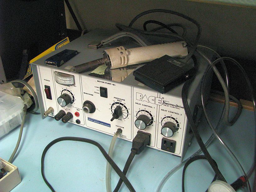
Jeff Liebermann <jeffl@cruzio.com>: Jan 30 06:12PM -0800

On Sun, 30 Jan 2022 16:15:27 -0500, Ralph Mowery
 
>Very good.
 
Well, not so good. As usual, I proofread my stuff after I post it. I
should not have included a solder sucker. That's fine for old PCB
boards with fat (1oz) and wide (0.1") traces. However, today's SMD
PCB's use much less copper and narrower traces. Try to suck solder
from a modern board, and the vacuum will suck the copper trace along
with the solder. Best to leave the solder sucker out of the list.
 
>you want to remove the part. Get some very fine solder of the tin/lead
>type and one of the flux despensers that looks like the covid shot
>needle. Flux is your friend.
 
Aluminum foil is cheaper, reflects the heat, bends around corners and
conforms easily to odd shaped areas and parts. I have rolls of the
really fine 0.021 lead/tin solder, but I never seem to use it. I've
settled on Kester 44 rosin core 63/37 in 0.050 and 0.062.
 
>Some of the desoldering braid comes in
>handy.
 
I haven't had much luck using braid for SMD PCB's. Too much danger of
overheating and destroying the pads. Braid is useful for connectors
and cleaning up the mess when I use too much solder.
 
>I have one of the hot air stations like you show and it works well for
>the hobby.
 
Old, but reliable:
<http://www.learnbydestroying.com/jeffl/crud/pace-desoldering-station.jpg>
I have two others (but no photos).
<https://www.ebay.com/itm/353259898775>
and one that was a prototype for a product that never was put in
production. When I closed my office in late 2020, I dragged most
everything home. I also emptied my Subaru, which was acting as a
service "truck". So, I now have two or three of everything.
 
 
>The Amscope se400 for about $ 235.
 
>Without the scope you can plan on spending around $ 100 to $ 150 for all
>the things you should need.
 
I'm 74 years ancient. The hands are still steady but the eyesight is
becoming a problem.
 
Agreed. I have a small collection of assorted microscopes.
<http://www.learnbydestroying.com/jeffl/pics/microscopes/index.html>
For PCB work, I use an Olympus SZ30:
<http://www.learnbydestroying.com/jeffl/pics/microscopes/Olympus%20SZ30/index.html>
Also, you might need a stand. This one weighs about 40 lbs:
<http://www.learnbydestroying.com/jeffl/pics/microscopes/Olympus%20SZ30/index.html#SZ30-01.jpg>
 
Look for a microscope that has as much working distance (between the
objective lens and the work piece) as possible. Don't buy a
biological microscope. Biological microscopes have all the fancy
features that you don't need for electronics and all have a tiny
working distances. If you are going to do much soldering under the
microscope, plan on getting a fan to blow away the smoke or cleaning
(or ruining) a few objective lenses including the one's on the turret
that you're NOT using.
 
You'll also need a ring illuminator. Not having to deal with shadows
is the main benefit. I have one of these:
<https://www.ebay.com/itm/271435251906>
If I buy another one, I'll get one that emits more light or has more
LED's. I also suggest using the microscope mirror light to illuminate
the PCB from below, looking through the PCB. With luck, that will
show broken traces, shorts, solder blobs, cracks etc.
 
Using a CMOS USB camera to see what I'm doing on a big LCD screen, was
not as wonderful as I expected. It takes some practice to look at a
screen, while soldering under a microscope. I need more practice.
Still, if I were shopping for a microscope, I would get a trinocular.
Be sure get a 0.5x reduction lens with the CMOS camera or the field of
view will be about 1/2 of what's available. Similarly, if you find a
monocular microscope with insufficient working distance, you can
double the distance with a 0.5x Barlow lens.
 
 
--
Jeff Liebermann jeffl@cruzio.com
PO Box 272 http://www.LearnByDestroying.com
Ben Lomond CA 95005-0272
Skype: JeffLiebermann AE6KS 831-336-2558
Stephen Wolstenholme <steve@easynn.com>: Jan 31 02:34PM

On Sun, 30 Jan 2022 18:12:46 -0800, Jeff Liebermann <jeffl@cruzio.com>
wrote:
 
>PCB's use much less copper and narrower traces. Try to suck solder
>from a modern board, and the vacuum will suck the copper trace along
>with the solder. Best to leave the solder sucker out of the list.
 
I used a piece of wire insulation on the end of my ancient solder
sucker that resulted in a longer but much narrower sucker tip.
 
Steve
 
--
Neural Network Software for Windows http://www.npsnn.com
You received this digest because you're subscribed to updates for this group. You can change your settings on the group membership page.
To unsubscribe from this group and stop receiving emails from it send an email to sci.electronics.repair+unsubscribe@googlegroups.com.

Digest for sci.electronics.repair@googlegroups.com - 2 updates in 1 topic

Phil Allison <pallison49@gmail.com>: Jan 29 03:39PM -0800

Drake Snow wrote:
==============
> Title says it all.
 
** Not really.
 
> about the size of a pin. I'm guessing that's for SMD. Other than the
> original tip, the other four have never been used. What about solder,
> thickness and alloy as well as iron temperature setting?
 
===========================
 
** Got any idea what the existing solder is ?
Pb/Sn ? Pb free ? Sn/Ag ? Other?
 
What are you thinking of using?
 
60/40 ?
 
 
...... Phil
legg <legg@nospam.magma.ca>: Jan 30 11:23AM -0500

On Sat, 29 Jan 2022 09:22:48 -0500, Drake Snow <sn4@comcast.net>
wrote:
 
>about the size of a pin. I'm guessing that's for SMD. Other than the
>original tip, the other four have never been used. What about solder,
>thickness and alloy as well as iron temperature setting? Thanks.
 
If you're not worried about destroying the removed part, then it
doesn't really matter - the focus should be on not damaging the
printed circuit hardware surfaces and tracking. Cut the legs off
the part and desolder them carefilly, one at a time. Dress the
pcb surface carefully and solder new parts, one leg at a time,
starting with a single leg to position the part properly.
 
Use thin tin-lead flux-cored solder and a tip size that matches
the job.
 
If you want to save the outgoing part, without hot air desoldering,
you can use a 2mill nickel-steel shim (removed from the old stick-
on security devices) fitted into an exacto knife handle to separate
desoldered pins one at a time, as the shim advances underneath each
spot-heated pin.
 
RL
You received this digest because you're subscribed to updates for this group. You can change your settings on the group membership page.
To unsubscribe from this group and stop receiving emails from it send an email to sci.electronics.repair+unsubscribe@googlegroups.com.

Digest for sci.electronics.repair@googlegroups.com - 1 update in 1 topic

Drake Snow <sn4@comcast.net>: Jan 29 09:22AM -0500

Title says it all. I have a few SMD repairs to do, but don't have much
to start with. Don't want to have to shell out big $ just to make a few
repairs. I already have one of the Ebay 60 watt adjustable irons that
had four tips included with it. One is cone shaped and comes to a point
about the size of a pin. I'm guessing that's for SMD. Other than the
original tip, the other four have never been used. What about solder,
thickness and alloy as well as iron temperature setting? Thanks.
You received this digest because you're subscribed to updates for this group. You can change your settings on the group membership page.
To unsubscribe from this group and stop receiving emails from it send an email to sci.electronics.repair+unsubscribe@googlegroups.com.

Digest for sci.electronics.repair@googlegroups.com - 13 updates in 6 topics

Jeff Liebermann <jeffl@cruzio.com>: Jan 27 10:52AM -0800

>Reason is the acrylic UV can only set with direct UV, and it doesnt
>stick like epoxy anyway.. but it is ok for some materials mostly
>transparent for obvious reasons.. C+
 
Compliments of Google search. I don't have any experience with any of
these:
<https://www.epoxies.com/products/uv-curable-illumabond/>
<https://www.epotek.com/products/uv-and-uv-hybrid-epoxies/>
<https://www.threebond.co.jp/en/product/search/?form=category-form&category=Adhesives&featuresfunctions=UV%20curing+UV-LED%20light%20source-curable>
<https://www.polymer-g.com/uv-led-curable-products/uv-led-curable-epoxy/>
More:
<https://www.google.com/search?q=uv+curing+epoxy>
 
I looked for something on eBay (US) and only found small bottles, with
gaudy labels, claiming to be epoxy, but more likely to be acrylic like
the stuff you purchased. Searching for UV cure resign produced more
of the same. I didn't see any industrial grade products, just lots of
jewelry and arts+craft products. No clue what's available in UK, but
I suspect that you might need to purchase it from the manufacturer or
distributor.
 
I don't know your application, but you might look at 3D printing UV
curable resin:
<https://www.google.com/search?q=3d+printing+uv+epoxy>
The problem is that I can't tell in most products whether "resin"
refers epoxy, acrylic, urethane, or something else.
 
Good luck.
 
--
Jeff Liebermann jeffl@cruzio.com
PO Box 272 http://www.LearnByDestroying.com
Ben Lomond CA 95005-0272
Skype: JeffLiebermann AE6KS 831-336-2558
liz@poppyrecords.invalid.invalid (Liz Tuddenham): Jan 28 09:21AM

> further done or measured but the potential is definitely there to DIY..
> Might try again with slow set epoxy where an instant semi cure would be
> really useful! Thanks again. C+
 
See if you can beg some that is reaching its end date from your dentist.
 
 
--
~ Liz Tuddenham ~
(Remove the ".invalid"s and add ".co.uk" to reply)
www.poppyrecords.co.uk
Chris Jones <lugnut808@spam.yahoo.com>: Jan 28 10:55PM +1100

On 28/01/2022 21:38, Charlie+ wrote:
 
> Hi Liz - now that is a good interesting suggestion - got an appointment
> on the 31st, I'll ask then! Also brings forth the thaught of mixing
> acrylic UV with glass isonomer as a trial route!! Thanks. C+
 
What is the green stuff used for solder mask? That is UV-curable and
perhaps it is epoxy. LPKF sells it in little packets like they use for
ketchup or mustard in a fast food restaurant (but much more expensive I
bet...) also it is green by default.
liz@poppyrecords.invalid.invalid (Liz Tuddenham): Jan 28 01:44PM

> perhaps it is epoxy. LPKF sells it in little packets like they use for
> ketchup or mustard in a fast food restaurant (but much more expensive I
> bet...) also it is green by default.
 
I seem to remember it smelt like epoxy when I tried soldering through
it.
 
 
--
~ Liz Tuddenham ~
(Remove the ".invalid"s and add ".co.uk" to reply)
www.poppyrecords.co.uk
liz@poppyrecords.invalid.invalid (Liz Tuddenham): Jan 28 01:44PM


> Hi Liz - now that is a good interesting suggestion - got an appointment
> on the 31st, I'll ask then! Also brings forth the thaught of mixing
> acrylic UV with glass isonomer as a trial route!! Thanks. C+
 
I think dentists use epoxy for some repairs and acrylic for others
(judging by the smell) so you will need to check that you get the right
one.
 
--
~ Liz Tuddenham ~
(Remove the ".invalid"s and add ".co.uk" to reply)
www.poppyrecords.co.uk
Jake T <jaketbone@steak.com>: Jan 28 08:36AM -0500

Hi. I currently have access to a compressor/ expander IC:
 
https://pdf1.alldatasheet.com/datasheet-pdf/view/65260/HYNIX/GL6552.html
 
I want to bypass the expander during testing. Page 3 there describes
each pin function. Pin 6 is "EXP Mute." It says for "L" state,
expander mute is executed; for "H" state, expander is executed. Does
this mean simply grounding pin 6 if I want to bypass the expander?
 
Thanks.
Chris Jones <lugnut808@spam.yahoo.com>: Jan 28 10:37PM +1100

On 27/01/2022 16:15, Mike S wrote:
 
> I was thinking the same thing. When I was a tech we used silver, and
> gold conductive epoxy to attach surface mount components. Once cured it
> was quite strong.
 
I like Creative Materials 125-15 conductive ink, but I can't recommend
it for this situation because the minimum order quantity is much too
large, and it has to be shipped and stored refrigerated, which makes the
freight expensive. It also needs to be cured at high temperature to make
it conductive (80 degress C will do but hotter is better). It isn't
mechanically strong at all, but it is very conductive and in practice
has a long shelf life if kept refrigerated, and is a one-part ink so I
can dispense small quantities with little waste.
 
For this job, the stuff for fixing windscreen de-misters ought to do and
is more widely available.
 
I think the carbon-based ink (Bare Conductive etc.) would not do for a
crystal oscillator, the resistance would be too high and it would hurt
the Q.
Charlie+ <charlie@xxx.net>: Jan 27 05:46PM

On Thu, 27 Jan 2022 03:10:21 -0800, Jeff Liebermann <jeffl@cruzio.com>
wrote as underneath :
 
> the curing process and final properties differ.
 
>Full disclosure: I've worked with UV curable cyanoacrylate adhesive,
>but not epoxy.
 
Thanks JL yes I know what I've already got! Acrylic - I needed a source
for genuine UV Epoxy as opposed to the sales speak epoxy which is'nt!
Reason is the acrylic UV can only set with direct UV, and it doesnt
stick like epoxy anyway.. but it is ok for some materials mostly
transparent for obvious reasons.. C+
Charlie+ <charlie@xxx.net>: Jan 28 08:26AM

On Thu, 27 Jan 2022 10:52:51 -0800, Jeff Liebermann <jeffl@cruzio.com>
wrote as underneath :
 
snip
>The problem is that I can't tell in most products whether "resin"
>refers epoxy, acrylic, urethane, or something else.
 
>Good luck.
JL Thanks some great links you found, much better than I managed to
find.. my education on the subject improves!
So I surmise:
Only industrial sources and prices - out of bounds for my uses!
Ultra short shelf life. Hours/Days only.
Probably actually made from hybrid acrylic/epoxy mixes.
 
Funnily enough the first thing I tried within a few minutes of getting
the eBay stuff and realizing it had no epoxy characteristics, was to mix
some with 5 min epoxy. Fully expecting it to be immiscible, amazed to
find it mixed fine and worked as a first shot experiment, semi cured
with UV 365nM immediately and set solid after elapsed time! Nothing
further done or measured but the potential is definitely there to DIY..
Might try again with slow set epoxy where an instant semi cure would be
really useful! Thanks again. C+
Charlie+ <charlie@xxx.net>: Jan 28 10:38AM

On Fri, 28 Jan 2022 09:21:23 +0000, liz@poppyrecords.invalid.invalid
(Liz Tuddenham) wrote as underneath :
 
Snip
>> Might try again with slow set epoxy where an instant semi cure would be
>> really useful! Thanks again. C+
 
>See if you can beg some that is reaching its end date from your dentist.
 
Hi Liz - now that is a good interesting suggestion - got an appointment
on the 31st, I'll ask then! Also brings forth the thaught of mixing
acrylic UV with glass isonomer as a trial route!! Thanks. C+
Phil Allison <pallison49@gmail.com>: Jan 27 03:14PM -0800

BboB wrote:
=============
> the amount of hiss, I don't think I'm going to be able to use this for
> the intended purpose.
 
> I welcome any suggestions here to solve this.
 
** You sure the frequency is clear ?
 
You might have a conflict with a DTV station.
 
 
..... Phil
BboB <electronix@ourd.net>: Jan 28 04:54AM -0500

On 1/27/22 06:49, Peter W. wrote:
 
> Without being judgmental, I never purchase anything from 'the bay' on the expectation that it actually works as described. Nor would I sell anything (a very rare occurrence) that I describe as 'working'.
 
> Peter Wieck
> Melrose Park, PA
 
What this turned out to be was somehow caused by the preamp. I switched
out the preamps and problem solved. There must be instability in the
original preamp somewhere. You were right, definitely audio related.
Thanks for the help.
Jeroni Paul <JERONI.PAUL@terra.es>: Jan 27 07:04PM -0800

I have an HiFi system SABA CT9810 (also sold as THOMSON VTM 2800/2900, CRK 1207, BRANDT MID 3000, TELEFUNKEN POWER PACK 200) where the volume control does not allow low enough volume levels, the first step sounds normal volume, the second is quite loud and above too loud for domestic use. It was like this when new, not a fault but a design issue. It uses a pair of LC7533 for digital volume control and a LA4280 power amplifier.
 
LA4280 circuit is exactly as depicted in its datasheet. Years ago I lowered its gain inserting 1K8 resistors in series with the capacitor at the feedback pins and now I decided to lower it even more with 4K7 resistors. That works and results in a much better volume control range but now I get strange squealings tuning AM radio.
 
LA4280 datasheet explains nothing but LA4270 datasheet says to insert these resistors to lower the gain, but recommends to keep it above 30dB. That would be 700 ohm resistors, I have gone much lower gain and it is now prone to oscillate with the AM radio. The rest of the functions sound fine (FM, phono, tape, aux) but I wonder if it could be oscillating anyway.
 
Of course I would like to find the schematic of this thing to know how it was supposed to work but couldn't find anything. This one could be some prototype unit or something. I don't find any fault or wrong/missing component, the circuits are built and work as per datasheet, it's just that seems incorrectly designed.
 
The LC7533 is fed with 1Vpeak line-level audio from the selector and it adjusts that from an almost invisible scope trace to the full 1V input. Its output goes straight to the LA4280 and a led vu-meter that displays within reasonable range, this is why I think the amplifier input has the intended level. The LA4280 has a gain of 100 that to me is way too high, a gain of 10 or lower would seem more reasonable.
 
So some questions. The LA4280 has two unused pins "Phase compensation", could these be used to make it stable at lower gains?
Any other idea? Maybe a resistor divider at the input? (I would have to add an extra coupling capacitor for that).
You received this digest because you're subscribed to updates for this group. You can change your settings on the group membership page.
To unsubscribe from this group and stop receiving emails from it send an email to sci.electronics.repair+unsubscribe@googlegroups.com.

Digest for sci.electronics.repair@googlegroups.com - 9 updates in 5 topics

BboB <electronix@ourd.net>: Jan 27 06:40AM -0500

I know the answer might seem obvious (getting closer, checking
connections, etc) but this has me stumped. I recently acquired an older
170 Mhz based Radio Shack wireless mic and receiver for an upcoming
event. I got it off of the bay and it was advertised as fully
operational, but of course it wasn't. There was no audio upon receipt,
and I had to change the mic wire from the electret clip on, to the
transmitter. That got it going, but I notice that I have a lot of hiss
in the receiver. I've tried moving closer, and I still have the hiss.
If I turn off the mic (put on standby), I still have hiss, although a
bit weaker as I was obviously getting some hiss from the mic which was
expected. However, the hiss that remains stumps me and I shouldn't be
getting it. Audio seems to be coming from the receiver fine, but with
the amount of hiss, I don't think I'm going to be able to use this for
the intended purpose.
 
I welcome any suggestions here to solve this.
 
Thank you!
"Peter W." <peterwieck33@gmail.com>: Jan 27 03:49AM -0800

Typically, hiss of the nature you describe - not related to transmission/reception - is due to a failing driver or output device in the audio section. Since it is most likely that these functions are on a single chip, and unless that chip is able to be identified and easily changed, you are right in your diagnosis. As it is obviously defective, you should go ahead and return it if possible.
 
Without being judgmental, I never purchase anything from 'the bay' on the expectation that it actually works as described. Nor would I sell anything (a very rare occurrence) that I describe as 'working'.
 
Peter Wieck
Melrose Park, PA
Jeff Liebermann <jeffl@cruzio.com>: Jan 27 03:10AM -0800


>https://www.ebay.co.uk/itm/284120960911
(...)
>My guess is that all the advertised 'EPOXY' UV glues on ebay and Amazon
>are actually Acrylic... anyone know better or for sure? C+
 
UV curing epoxy is quite real. The problem is I don't know what the
eBay vendor is actually selling. I suggest you look at the different
curing instructions for UV curing acrylic and epoxy in the article
below, and try to determine which one matches the product you
purchased.
 
"UV curing acrylic vs. UV epoxy"
<https://www.galindberg.se/blogg/uv-curing-acrylic-vs-uv-epoxy/>
Two common types of UV curing (light curing) adhesives
are those based on acylate and epoxy. Both are cured
using UV or blue light between 365 nm and 405 nm. The
difference between them lies in their chemistry. Both
the curing process and final properties differ.
 
Full disclosure: I've worked with UV curable cyanoacrylate adhesive,
but not epoxy.
--
Jeff Liebermann jeffl@cruzio.com
PO Box 272 http://www.LearnByDestroying.com
Ben Lomond CA 95005-0272
Skype: JeffLiebermann AE6KS 831-336-2558
Charlie+ <charlie@xxx.net>: Jan 27 06:48AM

Anyone happen to really know about this stuff?
I baught my example from ebay:
https://www.ebay.co.uk/itm/284120960911?ssPageName=STRK%3AMEBIDX%3AIT&var=585619831920&_trksid=p2060353.m2749.l2649
 
Says its epoxy resin in the ad. and it sets (hot) hard almost instantly
with strong UV, quite useful but its not epoxy and doesnt stick like
epoxy! Its Acrylic - it even says so on the bottle. Iv used other UV
gloops in the past from China and they are softer setting types and
definitely Acrylic.
I do know that epoxy UV set glue is available industrially, they use UV
to kickstart and then continue setting for a time afterwards. However my
guess is that these real epoxy types are probably very expensive and not
for general use!
Asked the seller and got the answer roughly, "well we have no complaints
and we sell loads of it" !
My guess is that all the advertised 'EPOXY' UV glues on ebay and Amazon
are actually Acrylic... anyone know better or for sure? C+
Mike S <mscir@yahoo.com>: Jan 26 09:15PM -0800

On 1/26/2022 2:37 AM, Chris Jones wrote:
> from Silabs that radio amateurs often use as a local oscillator - they
> are very simple to use and can produce whatever frequency you need. The
> frequency can be programmed with some arduino-type processor etc.
 
I was thinking the same thing. When I was a tech we used silver, and
gold conductive epoxy to attach surface mount components. Once cured it
was quite strong.
"ohg...@gmail.com" <ohger1s@gmail.com>: Jan 26 09:47AM -0800

On Wednesday, January 26, 2022 at 9:59:30 AM UTC-5, Peter W. wrote:
> Generally, my approach to cracked cases of this nature is to clean thoroughly, add a generous bead of JB-Weld, right up to and including filling the screw holes, allowing it to cure, then drilling out the holes as needed Haven't lost a patient yet. It may not be the prettiest of cures, but it has the overwhelming virtue of working well.
 
> Peter Wieck
> Melrose Park, PA
 
I'll kluge it together at some point, or retire the meter. Haven't decided.
 
In the meantime, I checked ebay to see if cases were available, and I found one with ---- a cracked battery door same as mine except both sides are cracked *and* it looks like someone already filled the back case with epoxy for a previous failure. Scroll down the pictures to see the battery door and rear case half. Clearly brittle. Here's a link to the auction and an imgur link of an auction pic that I saved in case anyone sees this years from now after the auction is gone:
 
https://www.ebay.com/itm/284258608974?hash=item422f22274e:g:3zAAAOSwIshgd~Is
 
https://i.imgur.com/KOnJnvJ.jpeg
 
I found a new case on line but its almost as much as the meter cost. <shrug>
Jeff Liebermann <jeffl@cruzio.com>: Jan 26 10:09AM -0800

On Wed, 26 Jan 2022 06:59:27 -0800 (PST), "Peter W."
 
>Generally, my approach to cracked cases of this nature is to clean thoroughly, add a generous bead of JB-Weld, right up to and including filling the screw holes, allowing it to cure, then drilling out the holes as needed Haven't lost a patient yet. It may not be the prettiest of cures, but it has the overwhelming virtue of working well.
>Peter Wieck
>Melrose Park, PA
 
Good idea. I've done case repairs that way. I have to be careful
which plastic I try to glue. Some of my epoxies don't want to stick.
JB Weld 50139 Plastic Bonder works well enough but takes a full day to
properly harden.
 
What I've been experimenting with is plastic welding. YouTube videos
showing how it works with a soldering iron:
<https://www.youtube.com/results?search_query=plastic+welding>
<https://www.harborfreight.com/80-watt-iron-plastic-welding-kit-60662.html>
I didn't do too well because the parts I was trying to weld were too
small or thin.
 
I also tried hot air. Something like these except I made my own tool:
<https://www.amazon.com/hot-air-welder/s?k=hot+air+welder>
I installed a tiny nozzle on my hot air desoldering station for the
welder. I also made a nozzle that heats along a straight seam. I
collected some plastic knife shavings from various junk plastic cases
found around the shop. No need to color match as all the welding is
going to be on the inside of the case. In general, hot air works, but
you have protect nearby parts with an aluminum foil heat shield. Also,
some practice is helpful.
 
I have the beginnings of a water gas (HHO) hydrogen generator and
torch, which will allow me to make a very narrow hydrogen weld. It's
been sitting for about 3 years waiting for me to finish the build. No
clue if it will weld nicely (or blow up the shop), but it looks
promising.
<https://www.youtube.com/results?search_query=HHO+generator>


--
Jeff Liebermann jeffl@cruzio.com
PO Box 272 http://www.LearnByDestroying.com
Ben Lomond CA 95005-0272
Skype: JeffLiebermann AE6KS 831-336-2558
Jeff Liebermann <jeffl@cruzio.com>: Jan 26 10:22AM -0800

If you have a 3D printer, you could make a replacement battery cover
(or have someone make one for you):
<https://www.yeggi.com/q/fluke+meter/>
<https://cults3d.com/en/tags/fluke%20multimeter>
<https://mito3d.com/en/3dmodels/search/fluke/all/all/latest/1>
I didn't see anything specific for the 177, but I might have missed
it.
--
Jeff Liebermann jeffl@cruzio.com
PO Box 272 http://www.LearnByDestroying.com
Ben Lomond CA 95005-0272
Skype: JeffLiebermann AE6KS 831-336-2558
"ohg...@gmail.com" <ohger1s@gmail.com>: Jan 26 11:46AM -0800

On Wednesday, January 26, 2022 at 1:22:16 PM UTC-5, Jeff Liebermann wrote:
> PO Box 272 http://www.LearnByDestroying.com
> Ben Lomond CA 95005-0272
> Skype: JeffLiebermann AE6KS 831-336-2558
 
Good idea Jeff. I searched on the link you provided and found this for a 179, but it looks like the 177 and is most likely the same piece.
 
https://www.thingiverse.com/thing:3867107
You received this digest because you're subscribed to updates for this group. You can change your settings on the group membership page.
To unsubscribe from this group and stop receiving emails from it send an email to sci.electronics.repair+unsubscribe@googlegroups.com.

Digest for sci.electronics.repair@googlegroups.com - 8 updates in 2 topics

Three Jeeps <jjhudak4@gmail.com>: Jan 25 09:15AM -0800

> Anyone having an issue with Fluke cases getting brittle? I have a 177 that had the battery cover crack in the screw boss area, and the other side won't hold a screw as the inside post is cracked. The plastic is brittle and reminds me of the aging of plastic in 1990s plastic television cabinets. My 85s never did this and I have a very old 77 that is still in perfect shape although it doesn't get a of use. The 177 is my daily meter and yes, it's fallen a few times.
 
 
Sorry to hear.
I have 3 fluke multimeters: a 77(30 yo?), 179 (6-7 yo?), and 289 (~2 yo). None of them have the issues you describe. The 179 is my daily driver most of the time.
Surprising that the aging plastic issue would crop up on a Fluke.
For the inside post repair, you may want to consider, if there is enough space, to slide over a plastic sleeve filled with epoxy to reinforce it? Then use a slightly oversized screw?
Heat-shrink sleeve over post perhaps?
good luck
J
"ohg...@gmail.com" <ohger1s@gmail.com>: Jan 25 01:54PM -0800

On Tuesday, January 25, 2022 at 12:15:06 PM UTC-5, Three Jeeps wrote:
> Heat-shrink sleeve over post perhaps?
> good luck
> J
 
I'm sure I could kluge up a fix (or just retire the meter - it's close to 10 years IIRC), but I was more curious if anyone else had seen this (yet?) The brittle plastic syndrome was bizarre and I'm wondering if I'm an early victim of this on Fluke meters. Years ago, I remember two guys bringing in a 32" Sony flat CRT TV for repair and heard the telltale snapping as they muscled the beast in the door. It literally came apart in their hands and the CRT fell out the front as they put it down.
Phil Allison <pallison49@gmail.com>: Jan 25 01:56PM -0800

ohg...@gmail.com wrote:
====================
> Anyone having an issue with Fluke cases getting brittle?
 
** Yep.
 
>I have a 177 that had the battery cover crack in the screw boss area,
>and the other side won't hold a screw as the inside post is cracked.
 
** All the posts for the back screws on my 70 series 2 have failed.
Plus the "clicker" on the ranges switch broke about 10 year back.
 
Bought the meter in about '95 - it failed completely 2 years ago.
Not a common problem with other DMMs I own,
 
 
..... Phil
Jeff Liebermann <jeffl@cruzio.com>: Jan 25 02:39PM -0800

On Tue, 25 Jan 2022 08:29:42 -0800 (PST), "ohg...@gmail.com"
 
>Anyone having an issue with Fluke cases getting brittle? I have a 177 that had the battery cover crack in the screw boss area, and the other side won't hold a screw as the inside post is cracked. The plastic is brittle and reminds me of the aging of plastic in 1990s plastic television cabinets. My 85s never did this and I have a very old 77 that is still in perfect shape although it doesn't get a of use. The 177 is my daily meter and yes, it's fallen a few times.
 
Any sources of ozone nearby, such as electric motors? A friend, who
owned a machine shop, used to have the same problem with meters after
a few years. However, we're not sure if it's the ozone or the machine
oil in the air that's causing the plastic to become brittle. I also
created some cracking in one of my Fluke meters when I repeatedly used
alcohol to clean the case.
 
This might be of interest:
<https://www.eevblog.com/forum/testgear/fluke-quality/>
Note the photo of the replacement metal hex standoffs for the broken
plastic.
 
At some point in the past, it became necessary to put additives in the
plastic to make it fire retardant. My guess(tm) is that this has
something to do with the crumbling plastic. Look on the inside of the
case for the acronym that indicates the type of plastic used in your
177.
<https://www.bpf.co.uk/plastipedia/abbreviations/Default.aspx>
 
--
Jeff Liebermann jeffl@cruzio.com
PO Box 272 http://www.LearnByDestroying.com
Ben Lomond CA 95005-0272
Skype: JeffLiebermann AE6KS 831-336-2558
Jeff Liebermann <jeffl@cruzio.com>: Jan 25 02:47PM -0800

On Tue, 25 Jan 2022 08:29:42 -0800 (PST), "ohg...@gmail.com"
 
>Anyone having an issue with Fluke cases getting brittle? I have a 177 that had the battery cover crack in the screw boss area, and the other side won't hold a screw as the inside post is cracked. The plastic is brittle and reminds me of the aging of plastic in 1990s plastic television cabinets. My 85s never did this and I have a very old 77 that is still in perfect shape although it doesn't get a of use. The 177 is my daily meter and yes, it's fallen a few times.
 
This might be of interest:
"Problem plastics, types of deterioration & where you find it"
<https://mmics.files.wordpress.com/2008/04/problem-plastics-check-list.pdf>
 
--
Jeff Liebermann jeffl@cruzio.com
PO Box 272 http://www.LearnByDestroying.com
Ben Lomond CA 95005-0272
Skype: JeffLiebermann AE6KS 831-336-2558
"ohg...@gmail.com" <ohger1s@gmail.com>: Jan 26 06:44AM -0800

On Tuesday, January 25, 2022 at 5:39:58 PM UTC-5, Jeff Liebermann wrote:
> <ohg...@gmail.com> wrote:
 
> >Anyone having an issue with Fluke cases getting brittle? I have a 177 that had the battery cover crack in the screw boss area, and the other side won't hold a screw as the inside post is cracked. The plastic is brittle and reminds me of the aging of plastic in 1990s plastic television cabinets. My 85s never did this and I have a very old 77 that is still in perfect shape although it doesn't get a of use. The 177 is my daily meter and yes, it's fallen a few times.
 
> Any sources of ozone nearby, such as electric motors?
 
Nothing out of the ordinary certainly. My older meters have been used in the same environment and never had this issue. I just checked my 40 year old Beckman HD100 that I keep at home. I pulled the back cover to replace the battery last night (overdue) and flexed the inside plastic parts of the case. Shows no sign of brittleness even when tested with a pocket knife.


> At some point in the past, it became necessary to put additives in the
> plastic to make it fire retardant. My guess(tm) is that this has
> something to do with the crumbling plastic.
 
 
That makes sense. Unfortunately. Another case of creating far more problems than it solves.
 
 
"Peter W." <peterwieck33@gmail.com>: Jan 26 06:59AM -0800

Generally, my approach to cracked cases of this nature is to clean thoroughly, add a generous bead of JB-Weld, right up to and including filling the screw holes, allowing it to cure, then drilling out the holes as needed Haven't lost a patient yet. It may not be the prettiest of cures, but it has the overwhelming virtue of working well.
 
Peter Wieck
Melrose Park, PA
Chris Jones <lugnut808@spam.yahoo.com>: Jan 26 09:37PM +1100

On 24/01/2022 04:01, -faver- wrote:
> needed, but not quite.  Assuming this crystal would even work, would a
> series trimmer cap allow me to adjust to the proper frequency?
 
> Thank you.
 
Bearing in mind that the thing cost you $1, you could try scraping away
at the glass around what is left of the crystal pin, to expose as much
metal as you can on the wire, and then joining on a fine strand of wire
with silver conductive paint (for example the type used to repair car
window de-misters). Once you have a good electrical connection, you can
cover the joint with 2-part epoxy (araldite etc.) to make it robust.
 
It is also possible to remove crystals from their metal can, it may
still work if you are careful and there will be much more wire to make
contact to inside the can.
 
If you think the thing is worth much more than $1, you can either order
a custom crystal or use a PLL frequency sythesiser chip like the ones
from Silabs that radio amateurs often use as a local oscillator - they
are very simple to use and can produce whatever frequency you need. The
frequency can be programmed with some arduino-type processor etc.
You received this digest because you're subscribed to updates for this group. You can change your settings on the group membership page.
To unsubscribe from this group and stop receiving emails from it send an email to sci.electronics.repair+unsubscribe@googlegroups.com.

Digest for sci.electronics.repair@googlegroups.com - 3 updates in 2 topics

"ohg...@gmail.com" <ohger1s@gmail.com>: Jan 25 08:29AM -0800

Anyone having an issue with Fluke cases getting brittle? I have a 177 that had the battery cover crack in the screw boss area, and the other side won't hold a screw as the inside post is cracked. The plastic is brittle and reminds me of the aging of plastic in 1990s plastic television cabinets. My 85s never did this and I have a very old 77 that is still in perfect shape although it doesn't get a of use. The 177 is my daily meter and yes, it's fallen a few times.
Tim Schwartz <tim@bristolnj.com>: Jan 24 12:36PM -0500

Hi there,
 
It's your lucky day. I just looked through my vast and powerful junk
collection and I have a crystal marked 39.160MHz. If you think it is
close enough, send me an e-mail with a US mailing address and I'll send
it to you for free. It is a pull from who-knows-what, and I do not
assure you that it is good. 5/32 thick, 13/32 wide, 17/23 tall. Leads
long enough to make it through a PC board.
 
Regards,
Tim
 
 
On 1/23/2022 12:01 PM, -faver- wrote:
-faver- <faver10@nospam.net>: Jan 25 07:01AM -0500

On 1/24/22 12:36, Tim Schwartz wrote:
> long enough to make it through a PC board.
 
> Regards,
> Tim
 
Thanks, but I don't think this will work. The native crystal was a
39.190 Mhz, so even with varactors or trimmer caps, I'd never be able to
get it to the frequency needed. So, unless you had a 39.190.....
 
Appreciate this, however!
You received this digest because you're subscribed to updates for this group. You can change your settings on the group membership page.
To unsubscribe from this group and stop receiving emails from it send an email to sci.electronics.repair+unsubscribe@googlegroups.com.

Digest for sci.electronics.repair@googlegroups.com - 10 updates in 2 topics

-faver- <faver10@nospam.net>: Jan 23 12:01PM -0500

I recently pick up a Radio Shack wireless mic at Goodwill for $1. I
could hear something in the receiver ratting, so I figured it wouldn't
work. I was right. It turns out that the receiver has two crystals:
10.245 Mhz and 39.190 Mhz. The 39.190 Mhz crystal was cleanly broken
away from the PCB and making the rattling when moved. Problem is that
the break was so close to the case that there's nothing left to solder
to, so I need a new crystal. I see one on the "bay" but about $10 by
the time shipping and tax are added, which sort of defeats the purpose
of a bargain. So, what about this crystal instead?
 
https://www.digikey.com/en/products/detail/abracon-llc/ABLS-13-0625MHZ-10-K4Q-T/2184092
 
 
Most likely the native crystal was working from a fundamental overtone
anyway. The frequency of the above one gets me close to the frequency
needed, but not quite. Assuming this crystal would even work, would a
series trimmer cap allow me to adjust to the proper frequency?
 
Thank you.
bilou <bilou@sfr.fr>: Jan 24 01:52AM +0100

Le 23/01/2022 à 18:01, -faver- a écrit :
> needed, but not quite.  Assuming this crystal would even work, would a
> series trimmer cap allow me to adjust to the proper frequency?
 
> Thank you.
 
Worth a try IMHO.
Think also on the possibility of slightly modifying the 10.245 or the
transmitter oscillator.
-faver- <faver10@nospam.net>: Jan 23 08:05PM -0500

On 1/23/22 19:52, bilou wrote:
 
> Worth a try IMHO.
> Think also on the possibility of slightly modifying the 10.245 or the
> transmitter oscillator.
 
Wish there was a schematic somewhere for these. The units themselves
are all over the net for sale. Doesn't look like they are the best
performers.
Phil Allison <pallison49@gmail.com>: Jan 23 05:44PM -0800

-faver- wrote:
 
===============
 
> Wish there was a schematic somewhere for these. The units themselves
> are all over the net for sale. Doesn't look like they are the best
> performers.
 
** So the mic is on 49 MHz - right ?
 
The crystal is an SMD type that just * fell* off the PCB ???
Please explain.
 
 
.... Phil
-faver- <faver10@nospam.net>: Jan 23 09:05PM -0500

On 1/23/22 20:44, Phil Allison wrote:
 
> The crystal is an SMD type that just * fell* off the PCB ???
> Please explain.
 
> .... Phil
 
Yes, 49 Mhz system. The crystal housing is HC-49/U. No, it didn't
fall, it looks to me like the leads corroded away right at the PCB. The
old yellowed glue is left behind with the imprint of where the crystal
was. I've read how corrosive some of these glues could be and I think
that's what destroyed the crystal leads.
Phil Allison <pallison49@gmail.com>: Jan 23 06:39PM -0800

-faver- wrote:
===========
> old yellowed glue is left behind with the imprint of where the crystal
> was. I've read how corrosive some of these glues could be and I think
> that's what destroyed the crystal leads.
 
** Absolutely !
 
Seen the exact thing, many times - in powered loudspeakers made by dB Technologies.
Damn "yellow peril" glue !
4MHz crystals in the DSP system * corroded * right off the PCB and the whole thing stops.
 
Do you have a matching receiver for 49.xxx MHz ?
 
IMO you repair idea sounds unlikely to work out - crystal oscillators are fussy and those models are narrow band, about 25kHz IIRC.

Mics on higher bands like 175MHz are often 250KHz wide.
 
FM wireless mics are non simple, but fun to fix.
 
 
.... Phil
-faver- <faver10@nospam.net>: Jan 24 04:35AM -0500

On 1/23/22 21:39, Phil Allison wrote:
 
> Mics on higher bands like 175MHz are often 250KHz wide.
 
> FM wireless mics are non simple, but fun to fix.
 
> .... Phil
 
Well, I do have a radio scanner. That's how I knew that the transmitter
at least was working. It seems to be on frequency although, consistent
with the reputation I read about these units, the audio frequency range
leaves a lot to be desired.
 
I absolutely hate that glue! I have a transceiver that stopped working.
On one of the daughter boards inside the unit, most of the
electrolytics were glued down with the stuff. I've been in the process
of recapping it because about half of the electrolytics are no longer
any good.
 
So you don't think using the overtone of the crystal I mentioned will
serve as a working substitute for the broken off one?
Phil Allison <pallison49@gmail.com>: Jan 24 02:24AM -0800

-faver- wrote:
---------------------
<
 
> > Mics on higher bands like 175MHz are often 250KHz wide.
 
> > FM wireless mics are non simple, but fun to fix.
 
> Well, I do have a radio scanner.
 
** As do I, very handy for such work
Long as it can do wide FM up to 1GHz.
 
 
> at least was working. It seems to be on frequency although, consistent
> with the reputation I read about these units, the audio frequency range
> leaves a lot to be desired.
 
** OK, you tricked me with your heading.
FYI:
 
A "wireless mic" is a * MICROPHONE * not a receiver.
Plus a crystal is way more likely to come to grief in a MIC !

> I absolutely hate that glue!
 
** Me too, been fighting it for decades.
 
Criminal that many makers keep on using the vile stuff.
Roland, Yamaha, Alesis, dB Tech, Rockit and host of others.
 

> So you don't think using the overtone of the crystal I mentioned will
> serve as a working substitute for the broken off one?
 
** Maybe worth a go.
 
But the narrow FM may be your downfall if the frequency is off by even 10kHz.


..... Phil
Gavino Geran <gavzgeran@gmail.com>: Jan 24 12:58AM -0800

On Thursday, November 26, 2020 at 7:30:36 AM UTC+8, Cyndi Tiger Dobrinic wrote:
Gavino Geran <gavzgeran@gmail.com>: Jan 24 01:05AM -0800

> Did you ever get a schematic because I need one for mine too.
> Can you send me one via email pdf
> sa...@netease.com
 
Hello Arfa could you please send me also the schematic diagram of bose wave radio Service Manual 260128-0001
 
Thank you and best regards
You received this digest because you're subscribed to updates for this group. You can change your settings on the group membership page.
To unsubscribe from this group and stop receiving emails from it send an email to sci.electronics.repair+unsubscribe@googlegroups.com.