- USB charger from car battery inside house when power goes out - 3 Updates
- Solution Manual Electronic Principles (8th Ed., Albert Malvino, David Bates) - 4 Updates
- Old plasma screen Y_SUS anomalies - 3 Updates
- Lightning Strike - 2 Updates
- wireless client bridge signal strength measurement - 1 Update
| Michael Terrell <terrell.michael.a@gmail.com>: Oct 06 11:06PM -0700 On Wednesday, October 6, 2021 at 4:21:31 PM UTC-4, Peter W. wrote: > > Peter, I've noticed that Jeff Angus hasn't posted lately. Any idea why? > Alive and well, still in Ranger, TX. Thanks, I was getting a bit concerned about him. He stopped replying to me when Hillary lost the election, so it wasn't worth the time for me to try to contact him. |
| Michael Terrell <terrell.michael.a@gmail.com>: Oct 05 09:46AM -0700 On Monday, October 4, 2021 at 12:15:29 PM UTC-4, Peter W. wrote: > We need to understand the purpose of this group - which is to give the most complicated and unsuitable possible solution to the simplest request entirely without reference to common sense, life-safety or cost. Peter, I've noticed that Jeff Angus hasn't posted lately. Any idea why? |
| "Peter W." <peterwieck33@gmail.com>: Oct 06 01:21PM -0700 > Peter, I've noticed that Jeff Angus hasn't posted lately. Any idea why? Alive and well, still in Ranger, TX. Peter Wieck Melrose Park, PA |
| John Doe <always.look@message.header>: Oct 05 08:59PM Google Groups spam... -- |
| Edward Hernandez <dtgamer99@gmail.com>: Oct 06 04:08AM The John Doe troll stated the following in message-id > The troll doesn't even know how to format a USENET post... And the John Doe troll stated the following in message-id <sg3kr7$qt5$1@dont-email.me>: > The reason Bozo cannot figure out how to get Google to keep from > breaking its lines in inappropriate places is because Bozo is > CLUELESS... And yet, the clueless John Doe troll has itself posted yet another incorrectly formatted USENET posting on Tue, 5 Oct 2021 20:59:14 -0000 (UTC) in message-id <sjieb2$1a2$1@dont-email.me>. mHD3cOq7pa9A |
| Rosana Mendes <rosanamendes1306@gmail.com>: Oct 05 08:40AM -0700 Em sexta-feira, 6 de agosto de 2021 às 16:43:23 UTC-3, martin kyatuur escreveu: > Hearing you soon > Thanks > martin Can you send me a solution manual of Albert Malvino 8th edition Electronic Principle thanks |
| Rosana Mendes <rosanamendes1306@gmail.com>: Oct 05 08:42AM -0700 Solution Manual Electronic Principles (8th Ed., Albert Malvino, David Bates) |
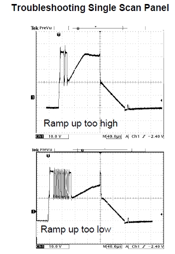
| legg <legg@nospam.magma.ca>: Oct 06 02:32PM -0400 On Wed, 6 Oct 2021 09:41:11 -0700 (PDT), "ohg...@gmail.com" >If you remove the IPM from the board and turn it over, you'll probably find the bottom is open but potted in clear snot. Careful visual inspection will reveal one or more blown open gates. Because I couldn't find a reliable source of IPMs, I started "repairing" them in a way. I used to isolate the bad mosfets from the IPM's ceramic circuit board and mount external ones to the underside of the heatsink, then wire them into the board. Here's a pic of the diagram I drew: https://i.imgur.com/TmQbULi.jpg >I used mosfets and they worked fine, but they did run hot so I always added a fan directly on the heatsink. Even when brand new, these ran stupidly hot anyway so even when I was able to source new boards or IPMs, I always added a fan to both sustain boards to prevent call backs. >The sustain boards are double sided, so removing the IPMs is a bit of a problem. I always preheated the boards and added liquid flux before attempting to suck the solder out of the holes. If you refer to the assumed switch configuration you'll see that the IPM has no connection to the only negative supply rail - its output is actually prevented from going negative by D14. If you refer to the output waveform, you'll see the IPM doing its think in the waveform's preliminary hash, where it switches quickly between Vs and gound. There are no other switches that can do this, except for those in the IPM. There were no blown fuses on this board, and the IPM shows highZ/bodyVf diode readings on the pins for SUS_OUT, VS and GND, when lifted. I had no trouble desoldering the IPM using a normal iron, one pin at a time, for removal. It has a solid black epoxy body - part number SPI-42X39090-2. The Y_SUS PCB is 3-layer. One of the 3 paralleled external fets had avalanched and gone resistive between gate and drain to overload -VY. With this was fixed, the buffer board seemed to pump -VY more negative than its regulated -200V, increasing to -250V or more to put the parallel fets into danger of avalanche). A new buffer board prevented this. The external heatsunk mosfets DO get hot. The two parts ID'd as 900V operate in their linear mode to develop the ramps, using a miller-cap/diode network between gate and drain. These two slopes are visible on the sick puppy's panel drive waveforms. I suppose that if the SUS_UP slope was slower and continuous, then a ~ book waveform could be created, using the end of drive period as the SUS-DN, per older 'return to -VY' methods. The book timing (40us/div) suggests that SUS-UP and SUS_DN are expected to complete in ~ (+)100us (-)80us time periods. Sick puppy's SUS_UP (50us/div) is too quick. The components in the 900V part's set-up miller network seem to be OK individually. Maybe if it was slower, the waveform might magically turn into a single pulse, rather than a double one. . . . . ? RL Still don't know why the buffer test point doesnt follow SUS_OUT. I'm working with a dark screen - a few pin-pricks of colour visible in a dark room. RL |
| "ohg...@gmail.com" <ohger1s@gmail.com>: Oct 06 09:41AM -0700 On Tuesday, October 5, 2021 at 8:31:15 PM UTC-4, legg wrote: > low, even outside of the drive period - simply bleeds > down to 0V, as illustrated. > RL If it still has some sort of picture, you probably blew the IPM under the big heatsink on the Z sustain module (right side). It should have blown one of the two 4A fuses on the board in any case, so check the fuses on both sustains. The IPMs are hard to find. I used to buy them in bulk out of China, but they were hit or miss: some were pulls, some worked, some didn't. If you remove the IPM from the board and turn it over, you'll probably find the bottom is open but potted in clear snot. Careful visual inspection will reveal one or more blown open gates. Because I couldn't find a reliable source of IPMs, I started "repairing" them in a way. I used to isolate the bad mosfets from the IPM's ceramic circuit board and mount external ones to the underside of the heatsink, then wire them into the board. Here's a pic of the diagram I drew: https://i.imgur.com/TmQbULi.jpg I used mosfets and they worked fine, but they did run hot so I always added a fan directly on the heatsink. Even when brand new, these ran stupidly hot anyway so even when I was able to source new boards or IPMs, I always added a fan to both sustain boards to prevent call backs. The sustain boards are double sided, so removing the IPMs is a bit of a problem. I always preheated the boards and added liquid flux before attempting to suck the solder out of the holes. |
| legg <legg@nospam.magma.ca>: Oct 05 08:33PM -0400 An older and poorly-documented plasma screen (LG 42PC3DV) apparently went 'pop' and developed dark screen. It had the usual bad 5V rail caps (x9) of the era (mfrd 6 months in 2006), and an overloaded -VY rail. I fixed those issues, to discover that Y_SUS waveform had no 'set-down' ramp. The mosfet generating that ramp can and does produce a -ramp, but only at the termination of the panel drive waveform, not within it. There is no gate drive signal, at the right time, to produce this ramp. It's complicated by the fact that models subsequent to this put zero volts across the panel outside of the drive period - up to that time the panel rested at -VY in most models. There are, of course, no schematics. The service manual includes only a module disassembly diagram and some vague flow charts. There are 'Troubleshooting' and 'Training' manuals for different models of the era, none of which include schematics of the power train or drivers, just the signal processing cctry. None have the same connectorization, harnessing, test point nomenclature/position. I'm counting on a 50PC1DR or 60PC1D training manual to give display waveforms for a 'return to -VY' system. There's a 42PC5DC, that exhibits the 'return to zero' system. None of the other power semiconductors are capable of pulling Y_SUS low - but there is no gate signal at the right time to do so. There also seems to be no factory reset procedure for these dinosaurs' firmware, that doesn't involve a special harness and PC software. Any ideas on getting this thing to perform? It's not for me, but seems to have sentimental value for the codger who put out kilobucks, in 2006, to own it. Assumed config of major switches- http://ve3ute.ca/query/42PC3D_Panel_Drive.jpg expected waveforms of similarly functioning models- http://ve3ute.ca/query/42PC5DC_Y_SUS_waveform.jpg http://ve3ute.ca/query/50PC1DR_Y_SUS_waveform.jpg Y_SUS of sick puppy- http://ve3ute.ca/query/42PC3D_Y_SUS_issue_211005a.jpg The scan buffer panel has been replaced once. It ~stores the SUS_UP peak, but does not follow the Y_SUS drive low, even outside of the drive period - simply bleeds down to 0V, as illustrated. RL |
| Ralph Mowery <rmowery42@charter.net>: Oct 05 01:42PM -0400 In article <lpuolg948p5oqen6jm8ddvsl9cd4t3l5m5@4ax.com>, jeffl@cruzio.com says... > with 2000 incoming minutes and 250 outgoing minutes included. That's > a net savings of about $420/year. I can also switch to all cellular > (cutting the cord) for which I alread pay $28/month. I like the POTS but my bill was similar to yours for just basic service. I Switched to internet phone and the internet together is $ 99 per month for the basic 200 speed download. I don't upload very much so do not care how how fast that is but do get 10 speed upload. With the internnet phone I get lots of what would be extra on the POTS like caller ID and long distance. I can even have it send the incomming call to my cell phone if I do not answer the home phone. |
| Jeff Liebermann <jeffl@cruzio.com>: Oct 05 10:03AM -0700 On Tue, 05 Oct 2021 00:01:18 -0400, Michael Trew >What region is this? I've heard several people tell me, especially out >west, that AT&T simply shut down the old ADSL out there, and resellers >and all couldn't sell it. I live in Ohio, former Ameritech region. USA, left coast, California, Santa Cruz county. I have not bothered to investigate the extent of the "legacy DSL" shutdown. I think it's national. Note the headline here: <https://www.att.com/internet/dsl/> "AT&T no longer offers DSL service" Clicking further down the page, it offers me up to 5 Mbit/sec service for $45/month plus taxes, equipment fees, hidden charges, and installation if needed. Why am I not thrilled? >> ADSL. In my case, it wasn't an option. >I like my POTS line.. if it ever become unreliable, or the price keeps >creeping up to an unreasonable level, I'll probably drop it. I also like POTS phone lines, mostly because they're far more reliable than anything that goes via the internet or cellular data. However, my latest AT&T POTS bill was $41.25 for flat rate, no long distance. I originate or receive perhaps 50 fairly short, non-telemarketting, phone calls per month making my cost about $0.80 per valid call. Meanwhile, I'm also paying $75/year for my former office VoIP phone from: <https://www.future-nine.com/plans.html> (Bare Essentials plan) with 2000 incoming minutes and 250 outgoing minutes included. That's a net savings of about $420/year. I can also switch to all cellular (cutting the cord) for which I alread pay $28/month. >moment.. as I was told, I can't move, change speed, etc.. but it still >works as of now. >https://www.dslreports.com/forum/r32848850-DSL-is-officially-grandfathered-Get-orders-in-BEFORE-October Yep. That's not what I received from my ISP. AT&T will continue to service legacy accounts for their AT&T customers, but not for the CLEC's, who have equipment located in their central offices and are leasing AT&T copper phone lines. >"Real speed" is about 2 down on any given test. It seems to work OK on >one device, streaming, browsing on one or two others. I doubt it could >do much more. Higher speeds (bandwidth) to have their advantages. For me, it was the ability to do more than one thing online at a time. I can now download a bloated Microsoft update, stream a movie (in 720p because I have a small TV and 1080p would be a waste of bandwidth), check my email, talk on VoIP or Zoom, etc all at the same time. 56Mbits/sec download, 6Mbits/sec upload. I've tried to overload the bandwidth and found it somewhat difficult because most (not all) of the streaming and video programs have some form of adaptive bandwidth management. Also, I use my routers QoS (quality of service also known as bandwidth management) settings to all the real-time stuff (mostly VoIP) to have priority. If you only do one thing at a time online, 2Mbits/sec might be adequate. 1.5Mbits/sec was adequate for me for about 20 years. However, if you're into multitasking your life, more bandwidth is a necessity. -- Jeff Liebermann jeffl@cruzio.com PO Box 272 http://www.LearnByDestroying.com Ben Lomond CA 95005-0272 Skype: JeffLiebermann AE6KS 831-336-2558 |
| Jerry <Jerry@JerryThinks.com>: Oct 17 01:03PM -0700 Is there any way to easily measure signal strength of a wireless client bridge? I have all the Android tools to measure signal strength of an access point. But they don't seem to display the signal strength of the client bridge. The client bridge was set up earlier this week by attaching an old Linksys WRT54Gv8.1 router (which I flashed to DD-WRT and set up as a client bridge) to an Ethernet-only old Win10 desktop (which didn't have a Wi-Fi card). Sitting at the Win10 desktop (with the client bridge sitting on top of that desktop) and logging into the Linksys DD-WRT interface shows the old Netgear home router signal is being received by the Linksys WRT56Gv8.1 client bridge at around -50dBm with the displayed "Signal Quality" graph coming out at around 65%. But how can I _measure_ (easily) the signal the other way around? How can I easily measure the signal strength of the client bridge at the home router? Is there an Android or Netgear or Windows tool to measure signal quality of the Linksys client bridge on the other end (which is back at the Netgear WNDR3400v2 home router)? Why do they give you tools only for easily measuring one side of the bridge? The Netgear Advanced > Administration > Attached Devices doesn't even show the client bridge. All it shows is the IP (and what I presume is the MAC address) of the Win10 desktop which is attached to the client bridge. But what Android or Windows tools tell us the strength of the client bridge? |
| You received this digest because you're subscribed to updates for this group. You can change your settings on the group membership page. To unsubscribe from this group and stop receiving emails from it send an email to sci.electronics.repair+unsubscribe@googlegroups.com. |
No Response to "Digest for sci.electronics.repair@googlegroups.com - 13 updates in 5 topics"
Post a Comment