- CRT question - 11 Updates
- Help identifying a blown transistor - 3 Updates
- Help hacking a laser tape measure? - 1 Update
| Jeff Liebermann <jeffl@cruzio.com>: Aug 25 10:37AM -0700 >>>>>So I built a kit that uses an electrostatic deflection CRT for the >>>>>display. It all turned out very well except the display is much more >>>>>in focus on one side of the screen. (...) >If not I can lock the display to just showing digits. Then I can >adjust the astigmatism and see if the digits on the right hand side of >the display get sharper. Is the scope really a kit? How old? I've had a bit too much entertainment value from old carbon composition resistors that absorb moisture and change value. It might be worth checking the resistance of some of the resistors in the focus/astigmatism circuit. For example, here's something similar caused by an open 332K resistor: <https://cromwell-intl.com/radio/tek2445a.html> This is going to be difficult without a schematic. If you run out of options, perhaps tracing the focus/astigmatism circuit, measuring voltages, and scribbling a schematic might be useful. >I can also swap the X axis wires, which mirror images the display. >I know because I already did this accidently. If the focus problem >mirrors too then I wonder what that would mean. I don't know for sure, but your logic seems sound. If the astigmatism problem remains the same, then the problem might be in the tube. If it changes when the X deflection leads are reversed, it's in the circuitry. >I'll try the astig. adjustment first later today. I've been trying to find a reasonable explanation of how the focus and astigmatism adjustments function. As near as I guess from what little I've found, the astigmatism adjustment compensates for axial symmetry errors in the electron gun. That brings up the possibility that the CRT might be sufficiently unsymmetrical to not allow astigmatism correction, or that the circuit or parts are so screwed up so as to not provide sufficient adjustment range. From the TEK 5440 manual: To check for proper setting of the Astig control, slowly turn the FOCUS control through the optimum setting with a signal displayed on the CRT screen. If the Astig control is correctly set, the vertical and horizontal portions of the trace will come into sharpest focus at the same position of the FOCUS control. ...front-panel FOCUS and internal astigmatism controls have been incorporated for arriving at an optimum CRT display. FOCUS control R440 provides the correct voltage for the second anode in the CRT. Proper voltage for the third anode is obtained by adjusting Astig control R370. In order to obtain optimum spot size and shape, both the FOCUS and Astig controls are adjusted to provide the proper electrostatic lens configuration in the CRT. So, how does the vertical astigmatism look? As bad as the horizontal or different? Not much help, but maybe it will offer some clues. -- Jeff Liebermann jeffl@cruzio.com 150 Felker St #D http://www.LearnByDestroying.com Santa Cruz CA 95060 http://802.11junk.com Skype: JeffLiebermann AE6KS 831-336-2558 |
| Jeff Liebermann <jeffl@cruzio.com>: Aug 25 10:51AM -0700 On Sat, 24 Aug 2019 20:04:54 -0700 (PDT), Jeff Urban >How can you build an electronic circuit without having the schematic ? I built quite a few Heathkit kits in the distant past that did not require the use of a schematic. A schematic was provided by Heathkit, but it was only useful for learning how everything works and for troubleshooting. I worked for a Heathkit store in the distant past for a few months. Most of what I found were the wrong parts in the wrong holes in the PCB. Occasionally, it was missing, extra, or substituted parts. Amazingly, I did find one design error. Heathkits spent considerable time and effort to avoid any assembly instructions or documentation errors. The unspecified manufacturer of this kit might not have been able to do as good a job. Methinks it might be worthwhile checking if there are any addendum, corrections, mods, or changes. I can usually find someone else's mistakes rather quickly, but have had less luck finding my own mistakes. Maybe having someone else check the CRT circuitry for assembly errors might be useful. Hint: That which is obviously correct, beyond any need of checking, is usually the problem. -- Jeff Liebermann jeffl@cruzio.com 150 Felker St #D http://www.LearnByDestroying.com Santa Cruz CA 95060 http://802.11junk.com Skype: JeffLiebermann AE6KS 831-336-2558 |
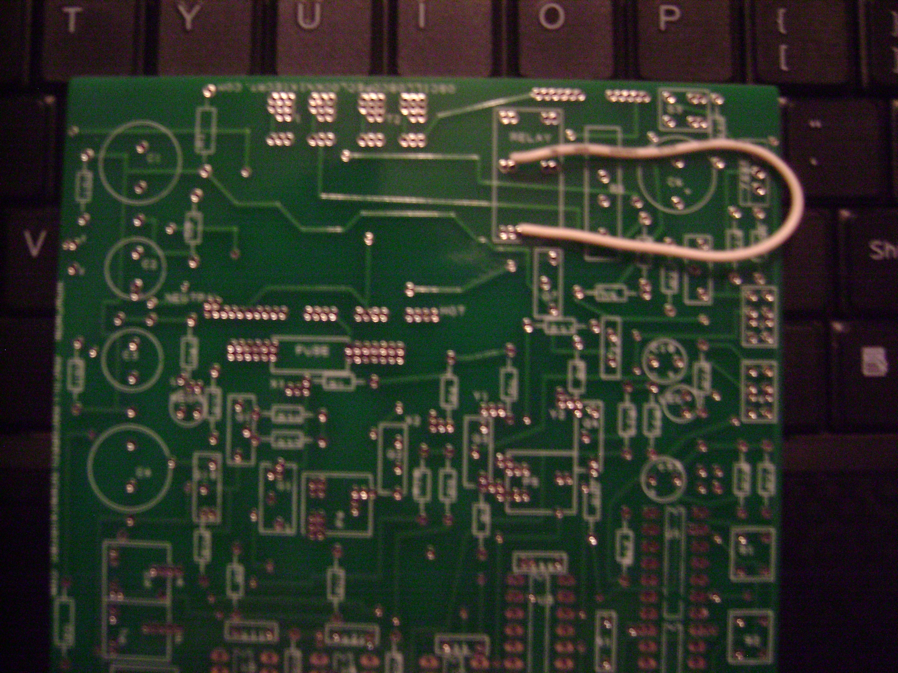
| etpm@whidbey.com: Aug 25 11:05AM -0700 On Sun, 25 Aug 2019 10:37:07 -0700, Jeff Liebermann <jeffl@cruzio.com> wrote: <SNIP> Yeah Jeff, it really is a kit. Here's the link: http://oscilloscopeclocknixiecrt.com/Kit.htm I wish I had traced out the circuit before I populated the board. But it's double sided and now really hard to see where traces go when they hide under components. Eric |
| etpm@whidbey.com: Aug 25 11:24AM -0700 On Sun, 25 Aug 2019 10:51:23 -0700, Jeff Liebermann <jeffl@cruzio.com> wrote: >check the CRT circuitry for assembly errors might be useful. >Hint: That which is obviously correct, beyond any need of checking, >is usually the problem. I did have someone check my work and he said it should work. And it does except for the changing focus. I am now thinking that somehow the voltages need to be changed. The heater voltage is just below the lowest voltage given on the spec sheet for the CRT. Nevertheless I am going to go back and check all the solder joints with a magnifier. And double check all the component values. The weird thing to me is that the thing works. It just goes out of focus gradually from one side of the display to the other. Thanks, Eric |
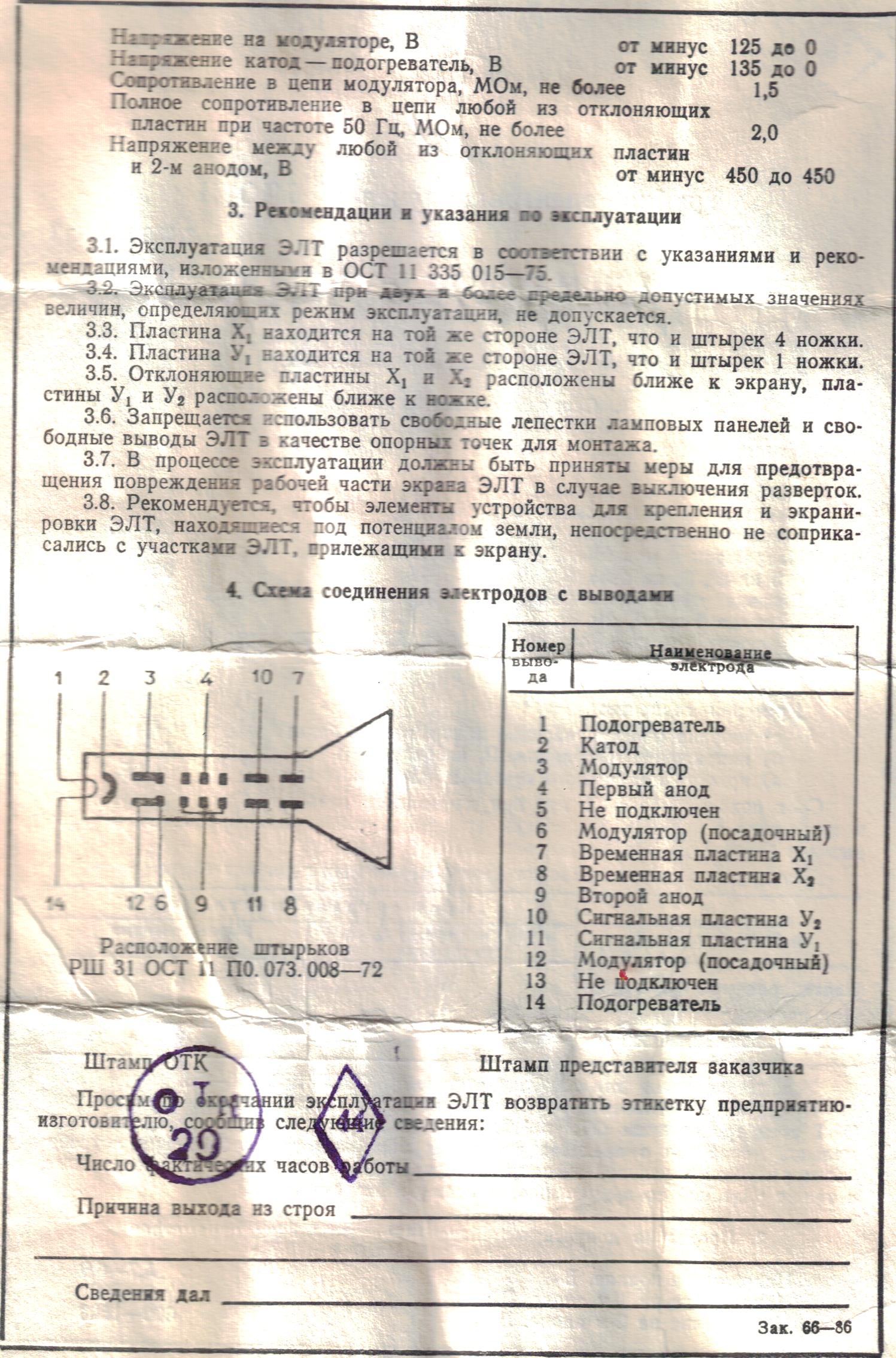
| Jeff Liebermann <jeffl@cruzio.com>: Aug 25 11:40AM -0700 ><SNIP> >Yeah Jeff, it really is a kit. Here's the link: >http://oscilloscopeclocknixiecrt.com/Kit.htm The video: <https://www.youtube.com/watch?v=y8ro4a65wk8> It looks ok. No astigmatism, but plenty of smear (hummm?) on the digits. However, the photos on the home page: <http://oscilloscopeclocknixiecrt.com> and Etsy: <https://www.etsy.com/listing/167965918/oscilloscope-clock-or-scope-clock-made> look much sharper. Which CRT tube are you using? The data sheet on the Russian CRT is not very useful: <http://oscilloscopeclocknixiecrt.com/OSC42/6Lo1_specs.jpg> There should be some test points on the PCB with Vert, Horiz, and Sync signals. Connect these to an oscilloscope and reproduce the display. My guess(tm) is that it will either be perfect, which simply validates that you assembled most of the PCB correctly, or full of hum or oscillations, which suggest a circuit problem. The aforementioned test won't do anything for testing the hi-v and CRT circuitry. However, there may be additional test points or inputs that can directly drive the vertical and horizontal amplifiers. This doesn't really prove anything or eliminate any possibilities, but it might be interesting to try. >I wish I had traced out the circuit before I populated the board. But >it's double sided and now really hard to see where traces go when they >hide under components. I like to shine a flashlight from the circuit side so that I can see the traces. However, you're right that it would have been easier to do with a bare PCB. Maybe you can convince the seller to send you a photo or paper copy of the PCB? Here's a useless out of focus photo of the component side: <http://oscilloscopeclocknixiecrt.com/OSC42/HVJumper.JPG> -- Jeff Liebermann jeffl@cruzio.com 150 Felker St #D http://www.LearnByDestroying.com Santa Cruz CA 95060 http://802.11junk.com Skype: JeffLiebermann AE6KS 831-336-2558 |
| Trevor Wilson <trevor@rageaudio.com.au>: Aug 26 06:14AM +1000 On 26/08/2019 1:57 am, Andy Burns wrote: > Trevor Wilson wrote: >> Try a Rigol DS1054z. A very impressive 'scope for not too much cash > And easily hackable to add extra bandwidth and features. **Yep. Buy the 50MHz model and convert it to 100MHz. Worst thing about the Rigol is the probes. Truly horrible probes. The worst I've ever used. -- Trevor Wilson www.rageaudio.com.au --- This email has been checked for viruses by Avast antivirus software. https://www.avast.com/antivirus |
| John Robertson <spam@flippers.com>: Aug 25 09:38PM -0700 > gradually from one side of the display to the other. > Thanks, > Eric Eric, have you tried contacting the kit maker? It may be a problem with the kit that he/she wasn't aware of - defective component, etc. It happens! 'howchon at hotmail dot com' (from the home page). John :-#)# -- (Please post followups or tech inquiries to the USENET newsgroup) John's Jukes Ltd. MOVED to #7 - 3979 Marine Way, Burnaby, BC, Canada V5J 5E3 (604)872-5757 (Pinballs, Jukes, Video Games) www.flippers.com "Old pinballers never die, they just flip out." |
| Jeff Layman <jmlayman@invalid.invalid>: Aug 26 08:05AM +0100 > it's double sided and now really hard to see where traces go when they > hide under components. > Eric Rather off-topic, but in one of the pictures (uncaptioned, about 2/3 to 3/4 of the way down, where the clock is on a stepped, wooden base) the valves are nicely coloured - green on the left, purple top right, and blue bottom right. I assume these are simply non-functional valves with a coloured led hidden in the base. Those are pretty unusual colours for leds; maybe a white led with a coloured filter has been used. And are the valves non-functional? I would expect the base to get pretty hot with the filament at that end. Not a good environment for an led. -- Jeff |
| Phil Allison <pallison49@gmail.com>: Aug 26 01:37AM -0700 Jeff Layman wrote: -------------------- > leds; maybe a white led with a coloured filter has been used. And are > the valves non-functional? I would expect the base to get pretty hot > with the filament at that end. Not a good environment for an led. ** Likely the valves are not operating and the rather bright light is coming from thin ,coloured filament bulbs - as used for xmas decorations and tree lighting. The hole in the bottom of a 9 pin valve base is not very big. .... Phil |
| tabbypurr@gmail.com: Aug 26 01:53AM -0700 On Monday, 26 August 2019 08:05:38 UTC+1, Jeff Layman wrote: > leds; maybe a white led with a coloured filter has been used. And are > the valves non-functional? I would expect the base to get pretty hot > with the filament at that end. Not a good environment for an led. LEDs in all sorts of oddball colours do exist, they're just a good bit more money & thus unpopular. NT |
| etpm@whidbey.com: Aug 26 09:13AM -0700 On Sun, 25 Aug 2019 21:38:25 -0700, John Robertson <spam@flippers.com> wrote: >the kit that he/she wasn't aware of - defective component, etc. It happens! >'howchon at hotmail dot com' (from the home page). >John :-#)# Yes, I did contact him. He has tried to help but so far nothing. Eric |
| janniebrand@gmail.com: Aug 26 03:11AM -0700 Hi Folks I have a Commax CDV-43k/DRC-4L (Stock Code: PI-1176) intercom that isn't working anymore. It seems the power supply board in the intercom (CDV-43K) itself (converting wall power of 220v to 15v) has blown. I think it might be the transistor (see photos: https://imgur.com/a/uBCXjwQ). The suppliers say that it is out of warranty and that I would have to buy a new one. Here is a link with a few photos of a circuit board that isn't working anymore: https://imgur.com/a/uBCXjwQ I have tried searching online, but couldn't find anything that gave me any indication of the specs of the transistor or what transistor to try and replace it with. I also tried to search for the schematic, but couldn't find anything. If anyone can perhaps help me identify the blown transistor or perhaps point me in the right direction that would be greatly appreciated. Let me know if you require any other information from me. Regards, Jannie |
| John Robertson <spam@flippers.com>: Aug 26 08:09AM -0700 > Let me know if you require any other information from me. > Regards, > Jannie Actually the PCB silkscreen indicates that this is an IC as it is called "U2", instead of a "Q" designation - Q for transistor and U for IC is a common convention. I would then suspect it may be a 15VDC regulator as this is some sort of switch mode power supply. John :-#)# -- (Please post followups or tech inquiries to the USENET newsgroup) John's Jukes Ltd. MOVED to #7 - 3979 Marine Way, Burnaby, BC, Canada V5J 5E3 (604)872-5757 (Pinballs, Jukes, Video Games) www.flippers.com "Old pinballers never die, they just flip out." |
| "pfjw@aol.com" <peterwieck33@gmail.com>: Aug 26 09:03AM -0700 On Monday, August 26, 2019 at 11:09:15 AM UTC-4, John Robertson wrote: > common convention. I would then suspect it may be a 15VDC regulator as > this is some sort of switch mode power supply. > John :-#)# And if this is the case, a TO-92 package, 15+ V regulator is here: https://www.newark.com/on-semiconductor/mc78l15abpg/ldo-voltage-regulator-15v-0-1a/dp/42K1178 Same source for a 15- V regulator as well. Peter Wieck Melrose Park, PA |
| N_Cook <diverse@tcp.co.uk>: Aug 26 10:47AM +0100 Looks like tenths *.1** is 9,5 for the previous determinations. Looks like processing for longer distances takes longer and timed-out for 20M samples so will have to select more when I rerpeat. Got display readings for 16.388, 26.766, 44.244 and 51.971m but full SPI only for the shorter pair . I've had a display reading of >70m on this when playing with the measurer on its own, so there is not an internal timing/bounding limit to 50m. Resolution to 1mm in 70m but its absolute accuracy , fixed positions and multiple readings, seems to be about +/-1cm over 50m for outdoor nighttime atmosphere. For the moment , as going above 10 involves coding changes in the Q and T sections and only 2 valid SPI readings so far, staying with the units decoding table of the previous and extending, maybe unit/tens ~ SPI R(1) , S (1) , T(1) 1~ 0,1,1 2~ 3,2,1 5~ 1,3,2 6~ 3,3,2 8~ 3,3,3 9~ 1,3,3 10~ 3,5,7 16~ 3,7,6 26~ F,B,6 The tenths decoding of the 16... and 26.... agrees with the previous. For eventual use, I'm only interested in the tens,units,tenths of metres and then 100/110/120m for the 120m version. -- Monthly public talks on science topics, Hampshire , England <http://diverse.4mg.com/scicaf.htm> |
| You received this digest because you're subscribed to updates for this group. You can change your settings on the group membership page. To unsubscribe from this group and stop receiving emails from it send an email to sci.electronics.repair+unsubscribe@googlegroups.com. |
No Response to "Digest for sci.electronics.repair@googlegroups.com - 15 updates in 3 topics"
Post a Comment