- 1920s radio - 9 Updates
- Help identifying a blown transistor - 7 Updates
| tabbypurr@gmail.com: Aug 26 07:22PM -0700 A little homemade 1920s 1 valve set with direct heated triode (unmarked). I've traced most of the circuit, looks very simple. Not tried to trace the main coil assembly with its 6 connections yet. The valve has a grid leak resistor for -ve bias without C battery. It runs high R phones, no speaker. 1st question is what sort of HT voltage and/or anode current should I aim for? NT |
| Arid ace <nonsmoker@freedom.smokes.oil>: Aug 26 10:24PM -0500 >A little homemade 1920s 1 valve set with direct heated triode (unmarked). I've traced most of the circuit, looks very simple. Not tried to trace the main coil assembly with its 6 connections yet. The valve has a grid leak resistor for -ve bias without C battery. It runs high R phones, no speaker. 1st question is what sort of HT voltage and/or anode current should I aim for? >NT One triode from that era is the A415. The datasheet lists Va between 20 and 150V, saturation current of 30 mA and default anode current of 3 mA. |
| John Robertson <spam@flippers.com>: Aug 26 10:21PM -0700 On 2019/08/26 8:24 p.m., Arid ace wrote: >> NT > One triode from that era is the A415. The datasheet lists Va between 20 and > 150V, saturation current of 30 mA and default anode current of 3 mA. Indeed, you need to know the tube value to be sure, but consider the cost of batteries of the day and thus the B+ is likely 45VDC or thereabouts. In those days some people made their own B+ batteries - way back when I was a kid digging through attics in Toronto (mid 1960s) for old battery sets I found a couple of home-made lead acid batteries that were glass test tubes about 8 inches long mounted in a wooden box and there must have been 15 to 20 in each case. Wish I still had them as they were classic home-brew stuff which I always loved from the battery age of radio. John :-#)# -- (Please post followups or tech inquiries to the USENET newsgroup) John's Jukes Ltd. MOVED to #7 - 3979 Marine Way, Burnaby, BC, Canada V5J 5E3 (604)872-5757 (Pinballs, Jukes, Video Games) www.flippers.com "Old pinballers never die, they just flip out." |
| Phil Allison <pallison49@gmail.com>: Aug 26 11:44PM -0700 John Robertson wrote: > test tubes about 8 inches long mounted in a wooden box and there must > have been 15 to 20 in each case. Wish I still had them as they were > classic home-brew stuff which I always loved from the battery age of radio. ** The "battery age of (tube) radio" extended well into the 1960s. Popular "portables" of that era used a pair of 45V packs for B+ and a large 1.5V dry cell for tube heaters - all made by "Eveready". Miniature 7 pin tubes like the 1S4 and 1R5 were used - along with a transformer supply for home use with a multi-finned selenium rectifier. https://www.radiomuseum.org/tubes/tube_1s4.html ..... Phil |
| "J.B. Wood" <arl_123234@hotmail.com>: Aug 27 06:44AM -0400 On 8/27/19 2:44 AM, Phil Allison wrote: > https://www.radiomuseum.org/tubes/tube_1s4.html > ..... Phil Hello, and I once owned a Red case 4-tube (1R5, 1U4, 1U5, 3Q4) Westinghouse H-496P4 AM-band portable that used a 67.5 volt B-battery. The radio had a large speaker and sounded real nice but that B-batt was expensive. Sincerely, -- J. B. Wood e-mail: arl_123234@hotmail.com |
| Jeff Layman <jmlayman@invalid.invalid>: Aug 27 01:40PM +0100 On 27/08/19 07:44, Phil Allison wrote: > Popular "portables" of that era used a pair of 45V packs for B+ and a large 1.5V dry cell for tube heaters - all made by "Eveready". > Miniature 7 pin tubes like the 1S4 and 1R5 were used - along with a transformer supply for home use with a multi-finned selenium rectifier. > https://www.radiomuseum.org/tubes/tube_1s4.html I've still got one of these, bought by my father in 1955: <https://www.radiomuseum.org/r/pye_p131mbq.html> It still works on mains (I doubt it would be possible to find a decent B126 90v battery today); I added a miniature earphone socket in the early 60s. What amazes me is that this cost £13 new at the time - the equivalent of around £345 today! -- Jeff |
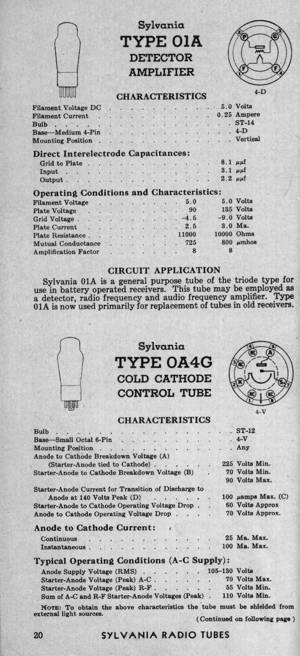
| "pfjw@aol.com" <peterwieck33@gmail.com>: Aug 27 05:45AM -0700 That will, very likely, be an Armstrong-circuit regenerative radio based on a common tube of the day, and what comes immediately to mind is the O1A, a 4-pin triode and good performer. Filament voltage is 5 VDC - polarity not critical. B+ will be 90 - 135 VDC Grid voltage will be -4.5 - -9 VDC http://www.bunkerofdoom.com/tubes/syl43/DATA/1943/P20.GIF Overall, those early triodes were not very efficient as compared to "modern" miniatures of the late 1940s and 1950s. Note that this basic design often included a variety of plug-in coils for conventional broadcast, SW and other bands as may have been available at the time. Keep in mind that 'official' regulation of land-based broadcast radio did not start (have teeth) in the US until ~1927. And, pretty much every Tom, Dick, Harry, church, department store and other organization had its own radio station, not to mention thousands of amateurs. So, the concept of staying with any given 'band' was not regulated. Peter Wieck Melrose Park, PA |
| tabbypurr@gmail.com: Aug 27 09:04AM -0700 On Tuesday, 27 August 2019 03:22:38 UTC+1, tabby wrote: > A little homemade 1920s 1 valve set with direct heated triode (unmarked). I've traced most of the circuit, looks very simple. Not tried to trace the main coil assembly with its 6 connections yet. The valve has a grid leak resistor for -ve bias without C battery. It runs high R phones, no speaker. 1st question is what sort of HT voltage and/or anode current should I aim for? > NT From all the replies it seems I don't know much, other than to set it for an Ia of about 2-3mA. It's a 4 pin valve with a modern shaped envelope, so could be anything. I guess it's a dull emitter replacing the original bright. There's no filament rheostat. The circuit details are different to the Armstrong version here https://en.wikipedia.org/wiki/Regenerative_circuit -it's definitely a reaction set, no doubt there. Apart from an input cap on the aerial there is NO other fixed cap anywhere in the circuit, so it's going to be horribly unstable, as if PFB on the edge weren't unstable enough already. I reckon it owes more to 19 teen design than to late 20s, so I expect a very early 20s set. I expect the ae coupling cap, tuning & reaction will all interact some - not to metion headphone wire position affecting feedback as well. It's gonna be a fun one to use. I presume the coil has a separate winding for the ae, and 2 more winds for the tank & pfb. PFB is controlled by a small varicap. It got rewired at some point with pvc. Can't imagine why. The connections are all 2mm sockets, which seems anachronistic, but everything else is definitely original. There's an extra hand wound coil that's only connected at one end. Can't see where it used to connect to. It connects to the ae input after the ae cap, and afaics the circuit ought to work fine without it in. Who knows. The ae cap pretends to be something else, it's only marked as "the new and improved... stabilizer portable aerial... for better listen" and terminals are marked A & B. Will do some component testing later. NT |
| John Robertson <spam@flippers.com>: Aug 27 09:10AM -0700 On 2019/08/26 11:44 p.m., Phil Allison wrote: > https://www.radiomuseum.org/tubes/tube_1s4.html > ...... Phil Yeah, but I was talking about the time when the primary home radio was a battery set - prior to battery eliminators and the like... I have a lovely (well, it was lovely at one time, the case needs all new leather) Radiola 24 which was an early 'portable' radio in my small collection. About the size of carry-on luggage these days. Cunningham C-299 tubes... John :-#)# |
| "jfeng@my-deja.com" <jfeng@my-deja.com>: Aug 26 09:47AM -0700 > Same source for a 15- V regulator as well. > Peter Wieck > Melrose Park, PA One more step you can take in an attempt to verify this hypothesis: you might remove the remaining epoxy from the chip and look at it under a microscope. I have seen some chips with part numbers in one of the metal layers. Or you could see that it is too complex to be a simple transistor and complex enough to be a regulator, or something in between like a Darlington. |
| Piotr Piatek <piotr433@pisi.com.pl>: Aug 26 09:16PM +0200 W dniu 26.08.2019 o 17:09, John Robertson pisze: > common convention. I would then suspect it may be a 15VDC regulator as > this is some sort of switch mode power supply. > John :-#)# It's likely a TL431, but I wonder how it could have blown so violently without some external help, as it is connected to the circuit through relatively high resistances? Piotr |
| Phil Allison <pallison49@gmail.com>: Aug 26 03:14PM -0700 > Here is a link with a few photos of a circuit board that isn't working anymore: > https://imgur.com/a/uBCXjwQ > I have tried searching online, but couldn't find anything that gave me any indication of the specs of the transistor or what transistor to try and replace it with. I also tried to search for the schematic, but couldn't find anything. ** Take about 15 minutes to trace that schem yourself. > If anyone can perhaps help me identify the blown transistor or perhaps > point me in the right direction that would be greatly appreciated. ** Looking at the copper side of the PCB, I can see the blown 3 pin device is driving the LED inside the opto-coupler for feedback. There is a small heatsink behind the chip, so a TL431 is a good bet. The opto will be cactus too. What happened ? Either the opto flashed over ( very rare ) or a foreign metal object did the trick. .... Phil |
| whit3rd <whit3rd@gmail.com>: Aug 26 04:05PM -0700 > I have tried searching online, but couldn't find anything that gave me any indication of the specs of the transistor... piotr and Phil are correct, it's probably a TL431 (or one of the many clones); to get it to blow up, takes lots of current (and probably another component was the cause). Install another TL431, another optoisolator (the four-wire black rectangle), and certainly check out the diodes (reverse voltage, if the diodes don't block it, could have done in the TL431). That looks like a single-sided phenolic circuit board; they can get damaged, so examination for cracks and some care about stress applied when under soldering heat are in order. The project can benefit from solder-wick and liquid flux. |
| janniebrand@gmail.com: Aug 27 02:38AM -0700 Thank you everyone for the amazing help so far. I'm learning so much with this. I feel like I should've perhaps mentioned that I'm pretty much a beginner when it comes to circuit boards. I've replaced fuses, capacitors and resistors before, after doing some research and finding the correct replacement parts, in order to bring back life to old/broken appliances/toys. Also, something else to note is that the local (Cape Town, South Africa) place where I get all my electronic parts is Mantech (https://www.mantech.co.za). That said, with regards to the Fixed Positive Voltage Regulator (15+ V) in a TO-92 package (as mentioned by John & Peter), I found the following options: https://www.mantech.co.za/ProductInfo.aspx?Item=14M8346 https://www.mantech.co.za/ProductInfo.aspx?Item=14M8345 https://www.mantech.co.za/ProductInfo.aspx?Item=14M4528 I've also followed the advice to remove the remaining epoxy from the chip and look at it under a magnifying glass (unfortunately I don't own a microscope). I have uploaded some new images (viewed through the magnifying glass) to the same link (the new pics are at the bottom): https://imgur.com/a/uBCXjwQ There seems to be no part numbers on the metal layers. I'm also not informed enough to know whether it is "too complex to be a simple transistor and complex enough to be a regulator, or something in between like a Darlington". To my untrained eye it seems pretty simple, so maybe a transistor then? With regards to the TL431 (as mentioned by Piotr, Phil & whit3rd), I could find a few options at Mantech, but not sure which one could work: https://www.mantech.co.za/Stock.aspx?Query=TL431and With regards to the opto-coupler (mentioned by Phil), I've added a photo of that as well (https://imgur.com/a/uBCXjwQ), the code on the opto-coupler is: L1620 817BL W @Phil: If I understood you correct, you are saying the because of the blown part, the opto is likely blown as well? If so, which opto should I try to replace it with: https://www.mantech.co.za/Stock.aspx?Query=817+optoand Unfortunately I have no idea what happened as I got this from someone that was throwing it out, since they had already replaced it. I'm trying to see if I can fix it. It is from the handset/monitor side of the intercom system, so maybe it came loose of the wall mounting and took a heavy knock? Also, we have had load shedding happening in the past, which would some times have caused voltage spikes when the power came back on. Don't know if that could've cause something like this to happen? I know people have lost appliances to that, but not sure if it could be related. @whit3rd: So you reckon, I just try to replace the blown part with a TL431 (any particular one from the list? https://www.mantech.co.za/Stock.aspx?Query=TL431and) and then also replace the optoisolator (any particular one from the list? https://www.mantech.co.za/Stock.aspx?Query=817+optoand)? I'll do a check of the diodes. Would testing in circuit be sufficient or should I remove the diodes from the circuit for testing? |
| janniebrand@gmail.com: Aug 27 03:12AM -0700 I did a bit of a detailed examination of the board with a magnifying glass for any possible damage. I found something on the back of the board that I hadn't noticed before (probably because of the blown part on the front). It seems like there might have been a short between a resistor (R20) and a diode (D4). I have taken some pictures and added it to the album (https://imgur.com/a/uBCXjwQ). Not sure if this helps or makes any difference, but let me know if there is anything else that I can check/try. |
| "jfeng@my-deja.com" <jfeng@my-deja.com>: Aug 27 06:57AM -0700 > enough to know whether it is "too complex to be a simple transistor and > complex enough to be a regulator, or something in between like a Darlington". > To my untrained eye it seems pretty simple, so maybe a transistor then? To my eyes, it looks like there is no remaining silicon there at all (maybe it got destroyed explosively when it blew off the epoxy) and all you have left are the wire leads. The wires alone do not tell you much. Can you trace out where the wires go? If it is a regulator, then the center lead will usually go directly to ground (nearly zero ohms to the negative output terminal). If it is a TL431, the left wire (looking at the flat surface with the wires down) will probably go to ground. And if it is a pass transistor, then probably none of the wires connect to the ground. |
| You received this digest because you're subscribed to updates for this group. You can change your settings on the group membership page. To unsubscribe from this group and stop receiving emails from it send an email to sci.electronics.repair+unsubscribe@googlegroups.com. |
No Response to "Digest for sci.electronics.repair@googlegroups.com - 16 updates in 2 topics"
Post a Comment