- Anyone have a trick for getting Husqvarna chainsaw brake kickback spring back on? - 14 Updates
- Manual head cleaning of HP 6520e printer - 1 Update
- Total Ripoff Pioneer Spares - 4 Updates
- Diode in series with the mains - 2 Updates
- Car alternator failure -- twice! - 1 Update
- Cambridge Audio Azur 640T DAB radio,2006 - 2 Updates
- CATV RF Notch Filter - 1 Update
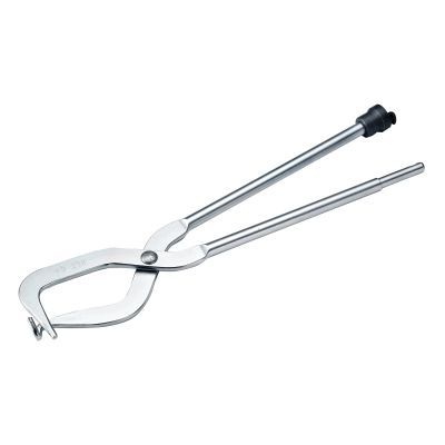
| Jeff Liebermann <jeffl@cruzio.com>: Feb 20 09:49AM -0800 >I think you mean "brake pliers". I have a set that is about to be >placed in service again for my drum brakes. ><http://www.matcotools.com/ProductImages/MST102B.jpg> Won't work. The problem is that one end of the spring has a nylon prong thing blocking the center of the spring. Even if you could compress the spring fully, there's no way to insert the nylon prong thing with the brake spring compression pliers in place. -- Jeff Liebermann jeffl@cruzio.com 150 Felker St #D http://www.LearnByDestroying.com Santa Cruz CA 95060 http://802.11junk.com Skype: JeffLiebermann AE6KS 831-336-2558 |
| "Phil Kangas" <pkangas@upalphacomm.net>: Feb 20 03:45PM -0500 "Jeff Liebermann" < > in place. > -- > Jeff Liebermann LMAO at all the responses! The only way to install it is to shoehorn it in. Go look in the silverware drawer, there may be a serving spoon in it with a rounded end of the handle to match the spring O.D. If the guy in the video can compress it with needle nose pliers then you sure can compress it with a shoehorn type tool! Sure that spring is strong but not _that_ strong. It is after all seated into a magnesium cover, how strong is that cover? And with the needle nose plier stunt, the spring can only be inserted half way putting a terrible strain on the lips of that mag. pocket! dannyd has already admitted to breaking his. So, good luck to you guys out there, I'm gonna shut my trap now and enjoy the comments... ;>)} BTDT |
| "Danny D." <dannydiamico@gmail.com>: Feb 21 12:03AM Phil Kangas wrote, on Fri, 20 Feb 2015 15:45:43 -0500: > dannyd has already admitted to breaking his. So, > good luck to you guys out there, I'm gonna shut my > trap now and enjoy the comments... ;>)} BTDT Well, I undid the tape and tried to straighten the spring in the saw itself, using the brake as the lever. But, I had to have the cover on halfway only (because it wouldn't fit over the drum due to the brake itself being contracted). And the spring sprung. So, now I'm back at the beginning. Step 1 is relatively easy (which is getting the spring in place). It's step 2 that's hard (loosening the brake). Will try again, but, with Jeff's video, I know what to do. It just has to be done without damaging the cover more than I already have. |
| "Danny D." <dannydiamico@gmail.com>: Feb 21 12:24AM Danny D. wrote, on Sat, 21 Feb 2015 00:03:37 +0000: > And the spring sprung. Ah, I see where I went wrong! Look at this video: https://www.youtube.com/watch?v=usP5XaXO7-8 The two steps are: 1. Getting the spring in (not too hard, once you get the hang of it). 2. Unlocking the chain brake (this is the harder part). What he did differently is that he left the duct tape on when using the chain brake to unlock the spring. I agree with him when he said at 1 minute and 35 seconds "good fuckin' luck" using the pliers to spin the chain lock clockwise to unlock the brake. I'm gonna try again, using the prybar method to get the spring in, and then the duct-tape method when unlocking the brake. |
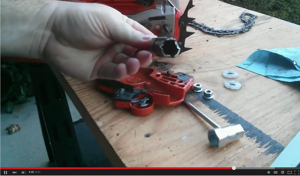
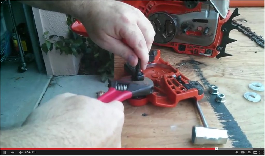
| "Danny D." <dannydiamico@gmail.com>: Feb 21 12:39AM Ralph Mowery wrote, on Thu, 19 Feb 2015 17:49:33 -0500: > I wonder if the Husqvarna people use somethink like that This is most likely the shape of the tool used to spin the brake release wheel! 1. https://c4.staticflickr.com/8/7439/16595963175_f4604227cf_b.jpg 2. https://c4.staticflickr.com/8/7391/16594779561_196d987d3c_b.jpg 3. https://c1.staticflickr.com/9/8677/16594779481_f7921a12ae_b.jpg Those are screenshots from this video: https://www.youtube.com/watch?feature=player_detailpage&v=KfQDjDBdq0Y#t=255 What the guy did was sacrifice a hole saw, by notching it to fit the chain brake spoke wheel. That seems to be the easiest method of all. |
| "Danny D." <dannydiamico@gmail.com>: Feb 21 12:49AM Danny D. wrote, on Sat, 21 Feb 2015 00:39:04 +0000: > This is most likely the shape of the tool used to spin > the brake release wheel! This is apparently the "official" method: http://blog.vminnovations.com/how-to-reset-husqvarna-chain-brake-fix-stuck-or-locked-brake-problem/ It seems so easy in that video. |
| Jeff Liebermann <jeffl@cruzio.com>: Feb 20 08:28PM -0800 On Sat, 21 Feb 2015 00:24:44 +0000 (UTC), "Danny D." >using the pliers to spin the chain lock clockwise to unlock the brake. >I'm gonna try again, using the prybar method to get the spring >in, and then the duct-tape method when unlocking the brake. I've only done this once, about 10 years ago, on a similar Husky chain brake mechanism. I had the same problem, where I couldn't compress the spring because one end had a plastic center prong blocking any kind of spring compression tool. So, I used some large pointed pliers, similar to what was used in the video. I didn't think of using a piece of scrap metal to old the spring in place, so I just put a 2x4 over the spring, and LOOSLY clamped the sandwich in a bench vice. The back end was propped up against the bench so that I could apply pressure to compress the spring. I had problems with the pliers, so I made a tool for the purpose. I slipped a small hose clamp around the pliers and placed a nail ahead of the hose clamp in the jaws of the pliers. The idea was that the nail would provide something to push against two sides of the spring while the hose clamp kept the nail from slipping. That worked. For rotating the chain lock, I shoved two screwdrivers on opposite sides of the mechanism, and rotated it with a larger third screwdriver as a lever arm. It was clumsy, but worked well enough. Or, you can make a special tool: <http://www.doityourself.com/forum/outdoor-gasoline-electric-powered-equipment-small-engines/346696-husqvarna-460-chain-brake-stuck.html> Of course, as soon as I released the bench vise jaws, the 2x4 fell out, and the spring went flying. So, I did it again, this time holding the 2x4 to the spring with a woodworking clamp. Eventually, I was able to slither the spring cover between the spring and the 2x4, reattach the screws, and live happily ever after. These might also help: <http://cr4.globalspec.com/thread/18020/Husqvarna-s-built-in-chain-brake-problem-repair-how-to> It's very long, but there's quite a bit of useful advice in there. <http://s51.photobucket.com/user/mantidontowel/profile/> Here's his method of spring compression: <http://s51.photobucket.com/user/mantidontowel/media/husqvarna/032408offhusqcorespondprocdureil-14.jpg.html?o=40> -- Jeff Liebermann jeffl@cruzio.com 150 Felker St #D http://www.LearnByDestroying.com Santa Cruz CA 95060 http://802.11junk.com Skype: JeffLiebermann AE6KS 831-336-2558 |
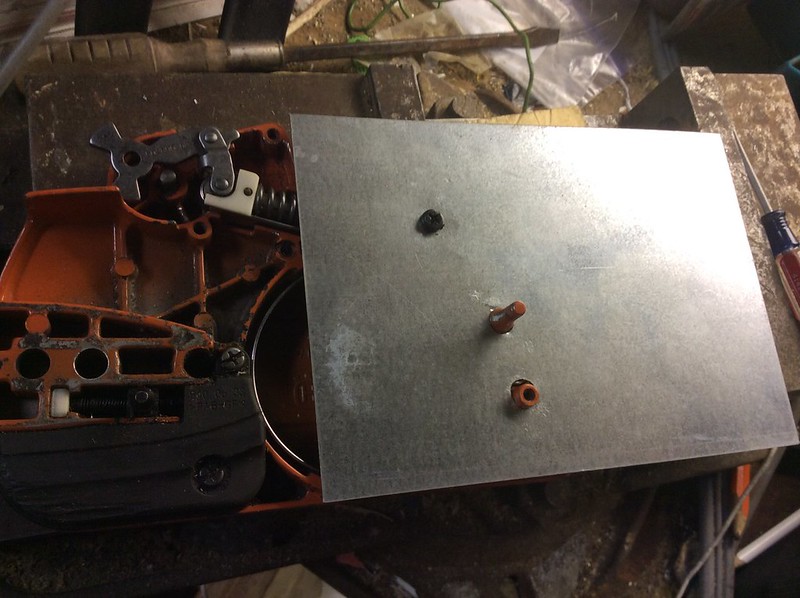
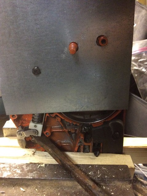
| "Danny D." <dannydiamico@gmail.com>: Feb 21 05:03AM Jeff Liebermann wrote, on Fri, 20 Feb 2015 20:28:20 -0800: > Of course, as soon as I released the bench vise jaws, the 2x4 fell > out, and the spring went flying. So, I did it again, this time > holding the 2x4 to the spring with a woodworking clamp. Hi Jeff, I solved it, sort of like how you did, thanks to your help and advice, and to the various suggestions in the videos (and to one innovation on my own that was shown nowhere else). While, in the end, I learned how to do it in just five minutes, it took probably a dozen attempts overall to come up with the following strategy using the four hints below, one of which was never described anywhere as I came up with it on my own). TRICK #1: Make a cover plate (as described in one video): https://c4.staticflickr.com/8/7453/16410601090_8172e71525_c.jpg TRICK #2: Make a female star tool (as described in another video): https://c4.staticflickr.com/8/7292/16411791159_84b7dd9775_c.jpg TRICK #3: Remove the circlip & pry up (not described in any video): https://c4.staticflickr.com/8/7289/16597628155_942786b3ea_z.jpg TRICK #4: Only use the cover plate for HALF the procedure! https://c4.staticflickr.com/8/7282/15975460464_8dbabda7ea_z.jpg After I built the tools for tricks #1 and 2, and after I came up with the unique procedure for trick #3, the final task, using trick #4 was trivially easy. While coming up with the procedure took hours, if I were to do it again tomorrow, with these tricks and tools, it would take about five minutes, and probably work the very first time. Thanks for all your help and advice. The video you provided kicked off all the good ideas. |
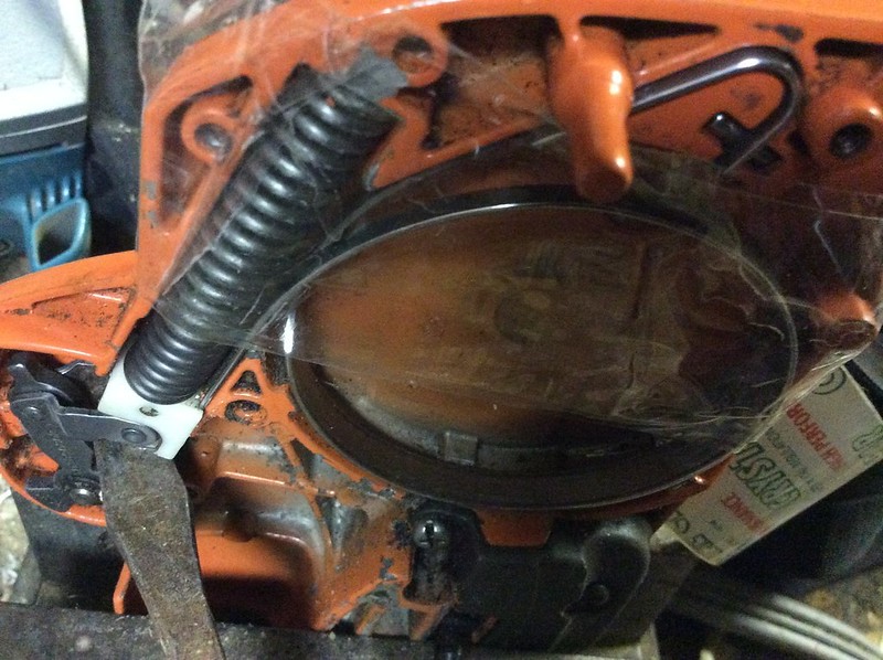
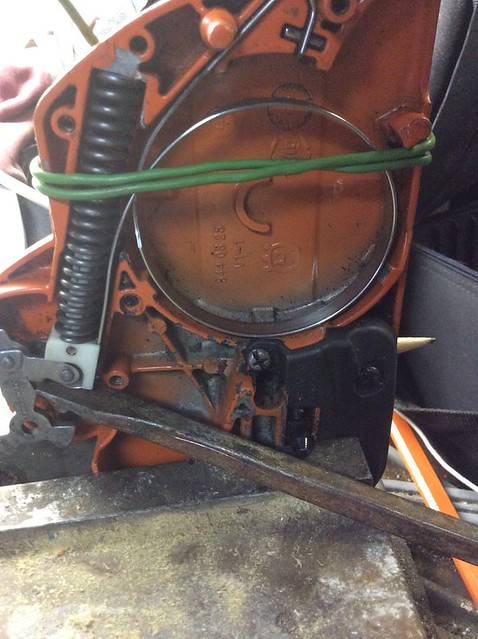
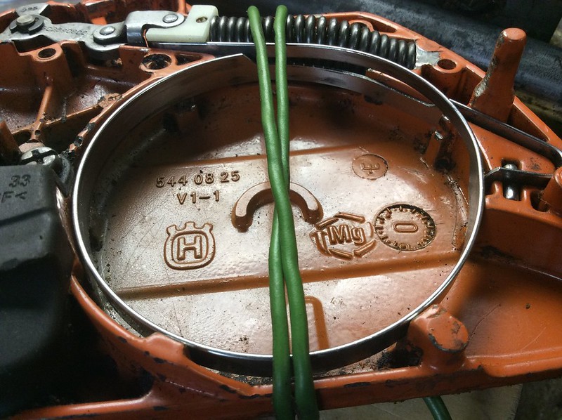
| "Danny D." <dannydiamico@gmail.com>: Feb 21 05:09AM Oren wrote, on Thu, 19 Feb 2015 15:19:51 -0800: > Your packing tape idea was interesting, so I figure it worked. Hi Oren, I had tried packing tape: https://c4.staticflickr.com/8/7306/16388881368_afb75a36fe_c.jpg I tried electrical wire: https://c4.staticflickr.com/8/7284/16597630615_ff28f652dc_z.jpg But, what worked best was making a temporary cover plate! https://c4.staticflickr.com/8/7453/16410601090_8172e71525_c.jpg Even so, that cover plate only works for HALF the procedure! The latter half, you use the original black plastic! https://c4.staticflickr.com/8/7351/16410598560_de1ffccf41_c.jpg Of course, that black plastic idea only works if you make a special female socket tool... https://c4.staticflickr.com/8/7292/16411791159_84b7dd9775_c.jpg |
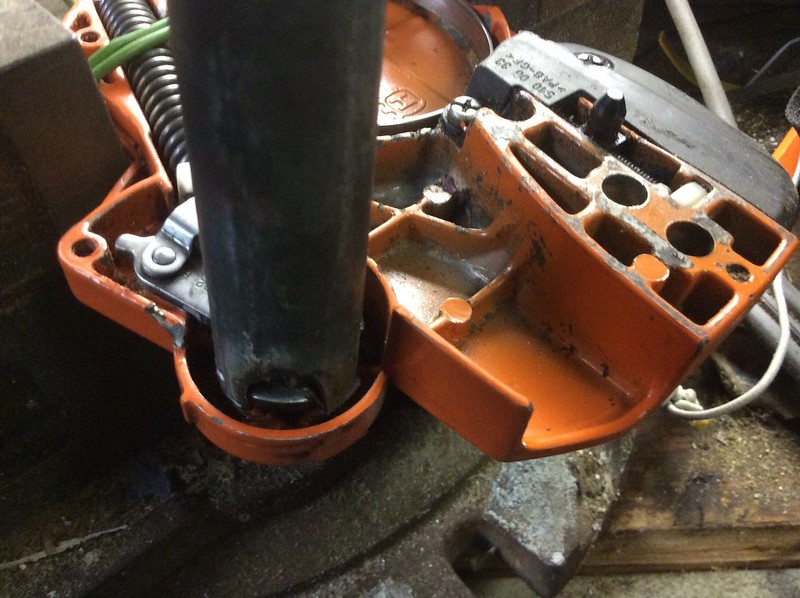
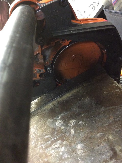
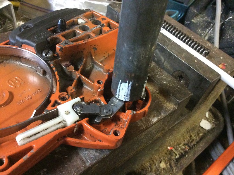
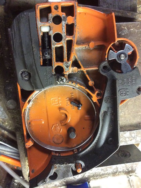
| "Danny D." <dannydiamico@gmail.com>: Feb 21 05:16AM Jeff Liebermann wrote, on Fri, 20 Feb 2015 20:28:20 -0800: > For rotating the chain lock, I shoved two screwdrivers on opposite > sides of the mechanism, and rotated it with a larger third screwdriver > as a lever arm. It was clumsy, but worked well enough. Hi Jeff, With a two-foot long pipe wrench and a special tool that I made, rotating the chain lock turned out to be very easy! https://c1.staticflickr.com/9/8565/15977856143_8e2d399445_c.jpg The problem was that the spring sprung the moment I removed whatever it was that was holding down the spring! https://c4.staticflickr.com/8/7339/16410601870_363e06db33_c.jpg I lost the spring EVERY SINGLE TIME I removed the covering holding the spring down! https://c4.staticflickr.com/8/7289/16571648146_b3f917358b_c.jpg The trick was to use the cover plate for only HALF the procedure! Without the female socket I made, it wouldn't have worked. But, once I realized how EASY it was to twist the chain lock with the tool I made, I then realized that the easiest solution was to put the black plastic holder back on first, and THEN twist the chain lock. Voila! The secret is having the right tools, and knowing the right sequence. For example, NOBODY came up with the idea of removing the circlip, which turns out to be the EASIEST way to get the spring into the first position. I'll write up a textual HOWTO so others can benefit. |
| Jeff Liebermann <jeffl@cruzio.com>: Feb 20 09:45PM -0800 On Sat, 21 Feb 2015 05:03:48 +0000 (UTC), "Danny D." >Thanks for all your help and advice. The video you provided >kicked off all the good ideas. Congrats. It might be helpful if I explain how I found the videos and other relevant links. I did NOT use Google web search. I used Google image search. Something like this: <https://www.google.com/search?tbm=isch&q=husqvarna+chain+brake+repair> Use your imagination for the buzzwords, but what's important are the pictures. Select anything that looks useful and see what appears. Same with YouTube videos. <https://www.youtube.com/results?search_query=husqvarna+chainsaw+brake+repair> Trying to do the same with a text search is much less useful. Incidentally, I just blundered across this video on the 455 that claims there's a "special tool" for reinstalling the brake spring. I'll ask the local dealer or rep for the specifics. It's no in the catalog. <https://www.youtube.com/watch?v=FjaVFLII4DE> -- Jeff Liebermann jeffl@cruzio.com 150 Felker St #D http://www.LearnByDestroying.com Santa Cruz CA 95060 http://802.11junk.com Skype: JeffLiebermann AE6KS 831-336-2558 |
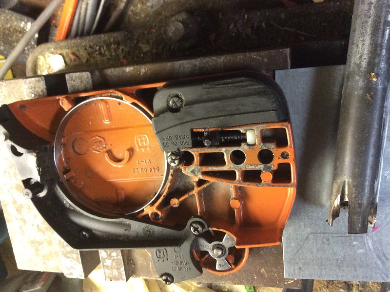
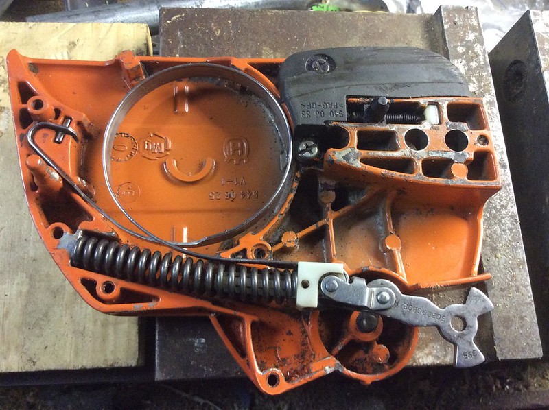
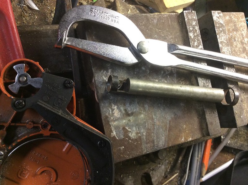
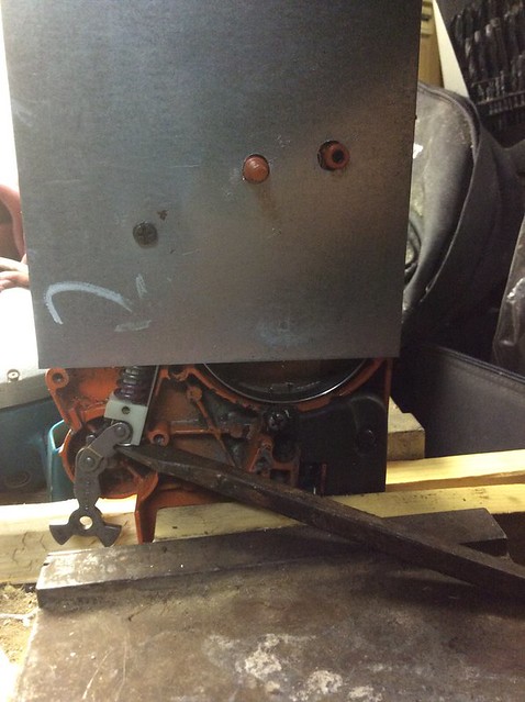
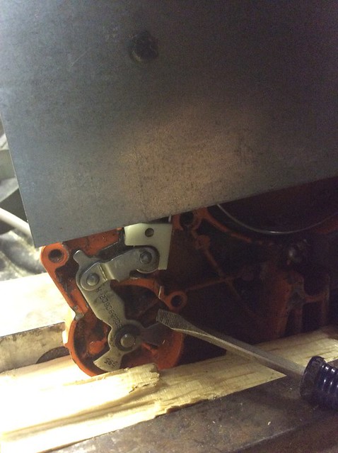
| "Danny D." <dannydiamico@gmail.com>: Feb 21 05:46AM Danny D. wrote, on Thu, 19 Feb 2015 02:52:28 +0000: > Anyone know the trick to get that super strong spring back on? Here's the 5-minute sequence, in a nutshell, once you know how to do it! - Remove the star-wheel circlip & position the spring in the slot. - Screw the temporary cover plate on (which holds the spring down). - Leverage the spring into position #1 (bent) with an 18-inch screwdriver. - Replace the circlip. - Remove the temporary cover plate (hold the spring down with your hands). - Replace the permanent plastic cover plates (watch the rubber post!). - Spin the star wheel into position #2 (straight) using a special socket. - Voila! Here's a more detailed pictorial DIY. It's easy, once you know these tricks and make the special tools! 1. Fabricate a female socket for the chainlock star wheel: https://c4.staticflickr.com/8/7395/16411792279_46ddab4f57_c.jpg https://c4.staticflickr.com/8/7397/16410603900_02b4cddeca_c.jpg Note: Forget about standard drum brake tools; they don't fit: https://c4.staticflickr.com/8/7339/16410598970_33a26618e9_c.jpg 2. Fabricate a hold-down plate for 1/2 the spring tensioning: https://c4.staticflickr.com/8/7453/16410601090_8172e71525_c.jpg 3. Lock the magnesium clutch plate upright in a vise and remove the circlip and pry up with an 18-inch screwdriver: https://c1.staticflickr.com/9/8571/16411787569_765c0f3a41_z.jpg 4. Replace the circlip once you have the spring in the 1st position: https://c4.staticflickr.com/8/7290/15977854503_6993ccff87_z.jpg 5. REMOVE THE TEMPORARY COVER PLATE! You can finish the job without removing the plate, but you'll lose the spring a half dozen times before you realize the folly of trying to get the spring into the second position with the cover plate on! If you're VERY LUCKY, you can get the cover plate off with the spring in the straight (second) position, but you MUST be very lucky for it to stay in place: https://c1.staticflickr.com/9/8579/16596438151_34b09b602e_z.jpg 6. Instead, remove the cover plate while the spring is in the first position and replace the black original plastic cover: https://c4.staticflickr.com/8/7351/16410598560_de1ffccf41_c.jpg NOTE: You can do this ONLY if you've made the special socket tool described in step #1. 7. With an 18-inch pipe wrench, spin the chainlock into the second (straight) position using the special socket tool you made in step #1: https://c4.staticflickr.com/8/7282/15975460464_8dbabda7ea_z.jpg 8. Do not make the mistake I made, which is to forget to put the rubber protection strip on the post UNDER the black plastic! https://c1.staticflickr.com/9/8580/15977853143_10b400741f_z.jpg I had it all done, and had to do it over again because of that simple faux pas (you can see the rubber endcap in the middle of this picture above; it's supposed to be inserted under and through the black plastic, so it has to go on 1st!). In summary, the tricks that make this task easy are: A. The socket tool allows you to spin the spring into the second (straight) position while the black plastic is on. This is immensely helpful because there is no danger of the spring springing out when you try to move from the temporary cover plate to the black plastic (ask me how I know this). B. The cover plate is still useful, in the first stage of spring compression, as it keeps both the spring in place, and it keeps the circular friction clutch in position. With tape and wire, the friction clutch moves out of position and is impossible to get back in place due to the enormous tension so you have to start all over again (ask me how I know). C. The cover plate is a hindrence for the second step, that of straightening the mechanism, becuase that adds tremendous additional tension, which springs the spring when you remove the cover plate. So, best to NEVER remove it, by replacing it with the permanent black plastic (ask me how I know). D. The unique trick of removing the circlip makes pushing the spring into the first position IMMENSELY EASY! There is no easier way to get the spring into that first position (ask me how I know). In all the videos, they left the circlip in place, and tried to compress the spring from the other end, but, it turns out to be easiest to PUSH on the spring from the attached end. Putting the circlip back on is easy, so the only danger is to be careful not to bend the brass pin and not to lose the circlip retaining ring. |
| "Danny D." <dannydiamico@gmail.com>: Feb 21 05:53AM Jeff Liebermann wrote, on Fri, 20 Feb 2015 21:45:30 -0800: > Congrats. It might be helpful if I explain how I found the videos and > other relevant links. I did NOT use Google web search. I used Google > image search. Hi Jeff, Thanks. I understand your search mechanism, and I see how it would work. I had searched google first and hadn't found the very nice videos you found, which gave me the ideas of the star socket and the temporary cover plate. I came up with the idea of removing the circlip on my own, and you can see in some of the videos what people thought of the idea of using the needlenose pliers (fat chance). With the combination of tricks, procedures, and special tools, the job is actually *easy*, although I did it at least a dozen times, because either the spring sprung out (most of the time) or I forgot to put the rubber post *under* the black plastic. Most of the trouble was getting the spring in place, and keeping it there, which is why the tricks and tools were needed. Thanks. I don't EVER want to do this again, but, if I do, I have the tools and procedures to make it easy. The real trick is to NEVER remove the clutch plate when the brake is on! |
| "Danny D." <dannydiamico@gmail.com>: Feb 21 06:03AM Danny D. wrote, on Sat, 21 Feb 2015 05:46:47 +0000: > - Replace the permanent plastic cover plates (watch the rubber post!). > - Spin the star wheel into position #2 (straight) using a special socket. > - Voila! BTW, in case someone asks, it's IMPOSSIBLE to turn the star wheel with just the special female socket tool. It still takes a lot of force, which is *easy* to apply using an 18-inch pipe wrench on the socket tool. But, without the pipe wrench leverage, you're never gonna spin that star wheel. Here's a list of tools required: - Special temporary cover plate (to hold down the spring) - Special female star socket tool (to spin the star wheel) - 1/8th inch screwdriver (to remove & replace the circlip) - #2 Philips screwdriver (to remove & replace the screws) - 18-inch screwdriver (to leverage the spring to position #1) - 18-inch pipe wrench (to leverage the spring to position #2) - Vise (to hold everything in place - this is mandatory!) |
| "Bob F" <bobnospam@gmail.com>: Feb 20 09:02PM -0800 Bob F wrote: > I have tried multiple cleaning cycles, and printing pages of all > black with no improvement. They print well except for about 1/8" gaps > horizontally every 1/2". Thinking about this, since it's one section of the entire print head that seem to be not printing, this might be more likely perhaps to be an electrical problem in the signals to the print head. Any opinions? |
| Trevor Wilson <trevor@SPAMBLOCKrageaudio.com.au>: Feb 21 11:18AM +1100 On 20/02/2015 7:09 PM, Jeff Layman wrote: > And you thought the Pioneer knob was expensive! A dozen years ago it > cost me over £70 to replace the 6 knobs on a Stoves unit (all the > markings had worn off, and a couple were loose). **It gets worse. I was working for a repair shop a few years back and we had to service a commercial microwave oven. The bearing for the stirrer had failed and we had to replace the stirrer and bearing as an assembly (along with the magnetron). The bearing was some kind of nylon material and the stirrer was, as usual, a light piece of bent aluminium. My estimated cost was about 5 Bucks (given the estimated manufactured cost would have been about $0.20). Actual cost of the stirrer was $140.00! All because it was a commercial MO. -- Trevor Wilson www.rageaudio.com.au --- This email has been checked for viruses by Avast antivirus software. http://www.avast.com |
| "Arfa Daily" <arfa.daily@ntlworld.com>: Feb 21 02:18AM "Gareth Magennis" <gareth.magennis@ntlworld.com> wrote in message news:9FrFw.650657$4b6.306270@fx44.am4... > Get this. A KNOB costs £15. > http://www.ebay.co.uk/itm/Pioneer-DJM-700-EQ-Grey-White-Rotary-Knob-DJM700-Low-Mid-Hi-DAA1219-/161064841103?pt=LH_DefaultDomain_3&hash=item2580366f8f > How do they get away with this? I repair quite a few of the CDJ and DJM units, and they are expensive to buy in the first place, but everyone that owns them loves them to bits. And because of this, I've found that they don't bat an eyelid at the cost of parts or the total repair costs. And the thing is that as you say yourself, it might just be a knob, but it's a unique knob that has that right 'feel' to it, so I suppose in some ways you can expect it to be expensive. The people that own these things are generally professional DJs, so these units are their tools that allow them, in some cases, to earn large amounts of money, so they expect to pay a premium to get them repaired. Arfa |
| Phil Allison <pallison49@gmail.com>: Feb 20 07:35PM -0800 Arfa Daily wrote: > people that own these things are generally professional DJs, so these units > are their tools that allow them, in some cases, to earn large amounts of > money, so they expect to pay a premium to get them repaired. ** Crikey !!! AD must deal with a whole different kind of "DJ" to the ones I come across. Words like "tight-arse", "con-artist", "hassler" and "whinger" cover most of them while the rest are straight out crims or drug dealers. ... Phil |
| "Martin Crossley" <Martin@g8uwm.NOSPAMabelgratis.net>: Feb 21 04:09AM Phil Allison wrote: > Words like "tight-arse", "con-artist", "hassler" and "whinger" cover > most of them while the rest are straight out crims or drug dealers. > ... Phil Aye, literally a world apart.... The knobs are indeed very dear for what they are, but at least they are available and not so outrageously expensive as to render the units Beyond Economical Repair for a fair charge for obtaining and fitting a couple of them. Martin. |
| "hrhofmann@sbcglobal.net" <hrhofmann@sbcglobal.net>: Feb 20 07:01PM -0800 Diodes I ever seen are always on the secondary side of the transformer. |
| Phil Allison <pallison49@gmail.com>: Feb 20 07:14PM -0800 > Diodes I ever seen are always on the secondary side of the transformer. ** Everyone is MISSING the point here. The *diode* in question is INSIDE the hot air gun !! Using it produces an ASSYMETRICAL load on the AC supply. That in turn produces a small DC OFFSET in the supply - maybe 0.5 to 1 volt. THAT in turn causes partial core saturation, particularly with TORROIDAL transformers, on the same supply circuit. When did a toroidal come into the picture ? WTF do you think a Variac is?? FYI" The Nutcase Kook Troll **NEVER** explains anything he posts. .... Phil |
| "Ron D." <Ron.Dozier@gmail.com>: Feb 20 02:41PM -0800 One of the things I do is to basically turn on the high power stuff and measure the (voltage drop) between the output terminal of the alternator and the battery. I keep that number around although now I have the ability to do non-contact measurements of current. That cable acts as a ammeter shunt, just not calibrated. It can be used as a benchmark, though. You could also have an engine ground bond broken. So thinks like looking at odd places like the wire to to stud when cranking. It might look like your measuring the same place, but in reality, your looking at the quality of the crimp. In a lot of cases the rotor gets powered from the ignition switch so that there is no leakage when off. So,, problems can be there too. So look at voltages across terminals under load and look for corroded bulkhead connectors. A very simple high resistance crimp is a possibility. |
| Sjouke Burry <burrynulnulfour@ppllaanneett.nnll>: Feb 20 05:59PM +0100 On 20.02.15 16:49, N_Cook wrote: > 9.6V ac from Tx is fine. Can only monitor supply side of one of those > 7805 and it dips below required, so hopefully it will be failed > smoothing electro, when I get to the other side of the main pcb. Well, do you like talking/responding to yourself? |
| "Gareth Magennis" <gareth.magennis@ntlworld.com>: Feb 20 09:16PM "Sjouke Burry" wrote in message news:54e76807$0$21155$703f8584@textnews.kpn.nl... On 20.02.15 16:49, N_Cook wrote: > 9.6V ac from Tx is fine. Can only monitor supply side of one of those > 7805 and it dips below required, so hopefully it will be failed > smoothing electro, when I get to the other side of the main pcb. Well, do you like talking/responding to yourself? I think you might find many quiet people listening. Gareth. |
| Jeroni Paul <JERONI.PAUL@terra.es>: Feb 20 09:09AM -0800 On some more traditional cable services the channels are transmitted in fixed frequency channels (MUX) usually 8Mhz wide just like air DTV. If the OP has such service it makes sense to add a filter to block that channel (but it may block other data that may cause the selection list to not work). It is not an ethernet like system but a DVB-C system. |
| You received this digest because you're subscribed to updates for this group. You can change your settings on the group membership page. To unsubscribe from this group and stop receiving emails from it send an email to sci.electronics.repair+unsubscribe@googlegroups.com. |
No Response to "Digest for sci.electronics.repair@googlegroups.com - 25 updates in 7 topics"
Post a Comment