- Refrigerator current load - 1 Update
- Baku 601D hot air reflow station - warning - 4 Updates
- UCC28061 bodge - 1 Update
- black microwave with diode not the problem - 1 Update
- can service manuals still be obtained through Radio Shack for RS products? - 2 Updates
- create schematic from circuit board images? - 2 Updates
- USA wiring question - 5 Updates
- USA wiring question - 1 Update
- for anyone looking for ANY service information! - 1 Update
| "Tom Del Rosso" <fizzbintuesday@that-google-mail-domain.com>: Feb 25 11:38AM -0500 amdx wrote: > lucky it didn't start a fire. I installed 220v to a sub box and > divided that for my freezers after that. > Mikek Yeah, thanks, but I realize that. It's the landlord's fault if the building burns. I have my own insurance. His might be cancelled. |
| legg <legg@nospam.magma.ca>: Feb 25 10:48AM -0500 I had a Baku 601D hot air reflow soldering station smoke on my bench over the weekend, with all switches 'off'. It's not CSA or UL (or anything else) It was a transformer failure. None of the front panel switches actually disconnect the line. Only protection was an 8A fast blow fuse. It had blown sometime before the plug was pulled, so I guess it did its job. The hot air gun is directly live through a triac circuit at all times that it's plugged in. I've rewound a new transformer, with a thermal link, higher temperature bobbin/wire. It will have its own fuse. Will also repurpose one of the front panel switches to disconnect the AC line and add a ground wire on the line cord. . . . . of course it's still not CSA or UL. RL |
| John Robertson <spam@flippers.com>: Feb 25 08:16AM -0800 On 2020/02/25 7:48 a.m., legg wrote: > cord. > .. . . . of course it's still not CSA or UL. > RL Typical Chinese junk - Amazon or eBay sourced I'm sure. You can't assume that even if it has a CSA or UL imprint/label that it actually is electrically safe as many of the labels are faked. Neither Amazon nor eBay are responsible for the safety of products sold through their portals, how did that happen? This is just a (cheap) time bomb waiting to go off - all the countless Chinese (etc.) made electrical junk. Back in the late 40s CSA and UL got their main boost from commercial TVs that exploded into flames. It shouldn't be too long now before it all starts happening again. Deregulation at its finest! John :-#(# |
| Ralph Mowery <rmowery28146@earthlink.net>: Feb 25 11:17AM -0500 In article <rdfa5f5259e4gmve33mr8p9f7mmi64ktvp@4ax.com>, legg@nospam.magma.ca says... > Will also repurpose one of the front panel switches to > disconnect the AC line and add a ground wire on the line > cord. Sounds like a lot of work for a $ 50 device. I have a 862D that is in the same price range. It does have a switch on the back that cuts off all the power. They are on ebay for around $ 55 depending on who you buy from. |
| Fox's Mercantile <jdangus@att.net>: Feb 25 10:32AM -0600 On 2/25/20 9:48 AM, legg wrote: > I had a Baku 601D hot air reflow soldering station smoke > on my bench over the weekend, with all switches 'off'. > It's not CSA or UL (or anything else) "Pay shit, get shit." -- "I am a river to my people." Jeff-1.0 WA6FWi http:foxsmercantile.com |
| legg <legg@nospam.magma.ca>: Feb 18 04:47PM -0500 An HPS lamp ballast on the bench came in with a shorted fet. This is in a UCC28061 two phase PFC that is designed for critical conduction. The design seems to follow the typical guidelines for the application, except that the drains of the two fets are shorted - completely bolloxing the concept of dual phase interleaving. Two fets, two boost inductors, two boost rectifiers, two independent zero-current-detection windings and drive circuits - but only one fet is driven at a time, with the other slogging the dv/dt and loading the node, with both chokes 'sharing' the current. The boost diodes can only share as well as such diodes might, when connected in parallel. Not a wide-range input circuit (240VAC only), but still using the book 300uH compromise inductor value. Concievably it still benefits from zero current switching, and at this high voltage, it's unlikely that much benefit would result from interleaving, but fet conduction losses have got to be 4x that of a single phase controller, with the same fets paralleled. Are there any other things to look out for in this kind of misapplication? It ran for about an hour with both fets replaced before the same fet position failed (phase B). No evidence of gross overheating. I see nothing wrong in the drive circuitry. The load is a conventional lamp inverter. I assume that a sudden inverter limit would produce standard overvoltage response in the 400V PFC circuit - fets are 600V. RL |
| delvon daily <delvondaily@example.com>: Feb 19 07:32PM -0600 Can you help me choose a microwave to fit the hole I already have? Especially how to get the exact size I need? And how important is "inverter technology? I need to replace a dead built-in black microwave without spending $800 to replace it with the original Jenn-Air M170B countertop 1200W 1.6cf unit. The existing fabricated black aluminum faceplate apparatus is pre-set to: Length = 22-1/8" Height = 13-3/8" Depth = 12-5/8" (but it can be deeper) Watts = 1200W Volume = 1.6cf Costco has a #1325470 Panasonic NN-SC668S for $119.99 Length = 20-7/16" Height = 12-3/8" Depth = 16" Watts = 1200W Volume = 1.3cf with something called "Inverter Technology". https://www.costco.com/panasonic-1.3cuft-stainless-steel-countertop-microwave-oven-nn-sc668s.product.100500583.html Home Depot has a #1003366983 Magic Chef for $109.00 Length = 20-3/4" Height = 12" Depth = 15-1/2" Watts = 1100W Volume = 1.6cf https://www.homedepot.com/p/Magic-Chef-1-6-cu-ft-Countertop-Microwave-in-Stainless-steel-with-Gray-Cavity-HMM1611ST2/305708071 Target has a #NN-SN67HS Panasonic for $119.99, which is Length = 20-11/16" Height = 12-1/4" Depth = 15-13/16" Watts = 1200W Volume = 1.2cf https://www.target.com/p/panasonic-1-2-inverter-microwave-stainless-steel-nn-sn67hs/-/A-52689506 Target also has a #072-1-282 Oster for $64.99 Length = 23.9" Height = 14.4" Depth = 18.4" Watts = 1000W Volume = 1.1cf https://www.target.com/p/oster-1-1-cu-ft-1000w-microwave-stainless-steel-ogcmdm11s2-10/-/A-53383982 |
| three_jeeps <jjhudak@gmail.com>: Feb 24 12:54PM -0800 On Sunday, February 23, 2020 at 9:32:20 PM UTC-5, All Bumbed Up wrote: > "partial" and I have no idea what that could mean. > Yes, some folks are lazy, but not this folk. Try finding it yourselves > if you dare. Yes, thank you. It did occur to me that you may have searched, but then it also occurred to me that since you gave no indication that you didn't, or provide any background/relevant information, I assumed it was lack of effort. Mia culpa. Then again, one could have provided just a terse answer as the question, or no response at all. It is a give and take thing...people that respond here take time to provide helpful information. Sometimes they go beyond 1-2 sentence responses and search/dig up information to help answer the questions. In order to do that,it is extremely helpful to know a base set of details and some clue of what the OP has done in order to solve their problem. good luck J |
| Jeff Liebermann <jeffl@cruzio.com>: Feb 24 06:17PM -0800 On Sun, 23 Feb 2020 21:32:15 -0500, All Bumbed Up >... but did >it ever occur that I already googled it, many, many times over the last >few weeks in fact? Nope. I appreciate your compliments, but members of this newsgroup are not normally blessed with clairvoyance, mind reading, and the ability to read between the lines. I do own a crystal ball, but it is in dire need of an unobtainium recharge and is therefore currently non-functional. While omnipresence (looking over your shoulder), and omniscience (knowing all things) are useful tools, not everyone can afford exchanging their eternal soul for these benefits. Therefore, it would be best if you supply the missing information needed to answer a question. May I suggest the following template: 1. What are you trying to accomplish? Not a detailed description. Just a one line general description of the problem so that the newsgroup gods might have a clue what you're doing. 2. What are you working with? That means names and numbers, not vague and ambiguous descriptions. Manufacturers name, full model number, revisions, firmware version, etc. As many numbers as you can find. Extra credit for providing a URL to the data sheet or service manual so we don't need to waste time finding the documentation. 3. What have you done so far and where are you stuck? Please do not assume that everything you've done is correct until you arrived at an impasse. It's highly likely that you did something wrong or badly. Notice that I'm not really interested in a detailed description of all the right or wrong things that you've done. Just a short list. 4. What level of ability and what test equipment are available? Notice that I didn't say "your level of ability" or "test equipment that you own". Just who do you have handy (including yourself) that can help with the problem, and what aids can you borrow? I'm not going to write a detailed test procedure only to find that you don't have access to any test equipment (or that the test equipment doesn't work). There are probably a dozen other things that would be of interest but the aforementioned are the most interesting. If you've invented something new, patentable, or believe that you're entitled to a Nobel Prize, you might reconsider asking questions. If you're working on a commercial project under NDA, and you value your job and bank account, I would also reconsider asking questions. Good luck and thanks again for suggesting that I can read minds at a distance (telepathy): Brain-To-Brain Communication Finally Achieved! <https://www.youtube.com/watch?v=ahxNdsW3yps> -- Jeff Liebermann jeffl@cruzio.com 150 Felker St #D http://www.LearnByDestroying.com Santa Cruz CA 95060 http://802.11junk.com Skype: JeffLiebermann AE6KS 831-336-2558 |
| All Bumbed Up <allbummedup@cao.net>: Feb 24 08:04PM -0500 This is a long shot, but is there any software out there that will take a circuit board with components and create at least a rough schematic from it? I realize that board and components would probably have to be overlayed. Just curious. |
| Jeff Liebermann <jeffl@cruzio.com>: Feb 24 05:53PM -0800 On Mon, 24 Feb 2020 20:04:35 -0500, All Bumbed Up >a circuit board with components and create at least a rough schematic >from it? I realize that board and components would probably have to be >overlayed. Just curious. Automation would be nice, but I do it by hand, with the aid of a computah to do the photo manipulation, drawings, and to connect the dots. Something like this: <https://www.instructables.com/id/How-to-reverse-engineer-a-schematic-from-a-circuit/> The difficult parts (for me) are identifying the components and photographing the PCB inside the original box, where the tangle of wires and mechanical parts usually get in the way. I've never tried to reverse engineer something as complex as the above example PCB. Even with simple PCB's, I always wiring errors and component errors. Plenty of articles and videos on other ways to do it: <https://www.google.com/search?q=circuit+board+reverse+engineering> I should probably read/view a few of these to see what I've been doing wrong: <https://www.google.com/search?q=circuit+board+reverse+engineering&tbm=vid> <https://www.youtube.com/results?search_query=circuit+board+reverse+engineering> Incidentally, if you have more than one of the PCB that you're trying to reverse engineer, I've found it better sacrifice one PCB to the electronics gods by removing all the parts and photographically reproducing the PCB. Once the holes are located and cleared with a solder sucker, it's easy to photo graphically locate the holes (light from behind the PCB). Then, using a continuity checker (buzzer or light), just connect the dots (holes) and you have a schematic. The hard part is to NOT rip out the plated through holes when removing the components. Chop off the component, leaving the leads. Heat the leads with an SMD hot air desoldering station, and pull out what's left of the lead with a pliers or tweezers. Then, clear the holes by heating the PCB, and either blowing solder slag all over your workbench, to sucking the solder out of the hole with a desoldering pump. Solder braid will tear up the pads and traces and should be avoided. Good luck. -- Jeff Liebermann jeffl@cruzio.com 150 Felker St #D http://www.LearnByDestroying.com Santa Cruz CA 95060 http://802.11junk.com Skype: JeffLiebermann AE6KS 831-336-2558 |
| etpm@whidbey.com: Feb 24 09:35AM -0800 Hey All, I have seen this done and I never questioned it but now that I was about to do it I'm wondering. In a well pump house there are always lights being run on 120 volts. The pump runs on 240 volts though. The breaker at the panel in the house that supplies power to the pump protects the heavy gauge wire running to the pump house. Inside the pump house is lighter gauge wiring running to the light. This wiring is connected to one leg of the 240 volt power and to the neutral. Does the 120 volt circuit need its own breaker in the pump house? I have never noticed one in any pump house I've been in, and I have been in several seeing as where I live most of the people I know are on a well. But I'm thinking code must require another breaker to protect the lighter gauge wire. Anyway, wiring in the pump house is on hold until I know the correct way. Thanks, Eric |
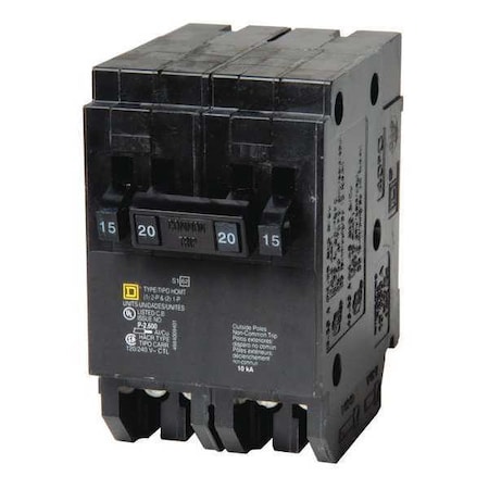
| Fox's Mercantile <jdangus@att.net>: Feb 24 12:04PM -0600 > Does the 120 volt circuit need its own breaker in the pump house? In a word, yes. 120 volt lighting typically is #14 AWG and requires a 15 amp breaker. 120 volt outlets should be #12 AWG and require a 20 amp breaker. A simple sub-panel in the well house with a "quad" breaker would be the simplest solution. <https://www.zoro.com/static/cms/product/full/Z1wBpzmcpEx_.JPG> -- "I am a river to my people." Jeff-1.0 WA6FWi http:foxsmercantile.com |
| "pfjw@aol.com" <peterwieck33@gmail.com>: Feb 24 10:05AM -0800 Main feed to breaker-box in pump-house. In breaker-box, one double-pole breaker to pump. One single-pole breaker to lights. One single-pole breaker to receptacle(s). Peter Wieck Melrose Park, PA |
| Ralph Mowery <rmowery28146@earthlink.net>: Feb 24 01:32PM -0500 In article <idWdnZ___5rWjcnDnZ2dnUU7-VvNnZ2d@giganews.com>, jdangus@att.net says... > A simple sub-panel in the well house with a "quad" breaker would be > the simplest solution. > <https://www.zoro.com/static/cms/product/full/Z1wBpzmcpEx_.JPG> I admitt that I do not have any idea about the code. However if it is just a simple light maybe it is like in most homes. The wire going from the actual light socket is often much lighter than the wire that is ran to it and the breaker is sized for. Main concern in most cases is that a true neutral wire and there is ground wire, or are they cheating and using the ground wire for the neutral ? |
| Michael Terrell <terrell.michael.a@gmail.com>: Feb 24 11:44AM -0800 On Monday, February 24, 2020 at 1:32:54 PM UTC-5, Ralph Mowery wrote: > Main concern in most cases is that a true neutral wire and there is > ground wire, or are they cheating and using the ground wire for the > neutral ? I have run into wells that ran the light from one side of the 240VAC, to the well casing. There was no neutral or ground wire run to the building. These were all built in the '64 and '65 time frame by the same well driller, and before there was a local building code for pump houses. My well pump has 240 for the pump, a 120V circuit for lights and another for a small heater. These are in a nearby laundry building, since there is no door on the pump cover. There is also a digital wattmeter for the pump, to see if it is running properly. |
| KenW <ken1943@invalid.net>: Feb 24 12:22PM -0700 >correct way. >Thanks, >Eric Search for > how does a 240v breaker work< both sides are protected KenW |
| All Bumbed Up <allbummedup@cao.net>: Feb 24 12:29PM -0500 After weeks of searching for at least a schematic for a couple of broken items, I finally came across a site that finally provided results: https://fccid.io/search.php Using FCC ID, I have been able to find out more than I originally intended! Try the site if you, like me, weren't making any headway through traditional searching methods! |
| You received this digest because you're subscribed to updates for this group. You can change your settings on the group membership page. To unsubscribe from this group and stop receiving emails from it send an email to sci.electronics.repair+unsubscribe@googlegroups.com. |
No Response to "Digest for sci.electronics.repair@googlegroups.com - 18 updates in 9 topics"
Post a Comment